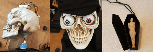
Lasersaur That Cuts 1/2″ Plywood And 10mm Acrylic (Pew-Pew)

Remember when building your own 3D printer was a big deal? We’re starting to think that building your own laser cutter might be the next hot topic.

Boasting a 16,000 square-foot facility, the Dallas Makerspace is an impressive collaboration of local artists, engineers, makers, and thinkers. Recently they embarked on building a serious laser cutting machine. They chose to go with the an open-hardware design rather than buying an off-the-shelf unit. What they built is based on the Lasersaur plans. (Another popular open-source build is the buildlog.net unit.)

They ended up with a huge 24″ by 48″ cutting bed and with a laser tube rated for 100 watts continuous output. It can cut 1/2″ plywood and 10mm acrylic with ease. The entire machine is built from 20mm Misumi aluminum t-slot extrusions, making more like a giant erector set then a commercial built machine. We hadn’t seen too many of the Lasersaur builds out in the wild, so we thought you might like to see one too.

Now, before you start ordering parts to build your own, you should know that a top of the line build like this will run you about $7-10k. But by comparison if you were to go with something with the same cutting area and power, you’d be looking at something like the “Epilog Fusion 40” at a whopping $40k. With that said, we expect to see more budget laser cutter builds. Cost can be cut dramatically when you go for a smaller machine, with less cutting area, and less power. With that, you can use less expensive steppers, drivers, and frame. We suspect a little as $700 for a smart shopper could yield a very respectable laser cutter.

If you’re interested in learning more about the Dallas Makerspace, we took a video tour back in early 2014.

tweet pinata

Tweet-Powered Bat Removes Effort Required To Obtain Pinata Contents

A child filled game-launch event was happening in London and [Roo] was asked to use his serious making skills to construct a machine that would hit a pinata with a baseball bat. This is a great idea, well, because giving bats to a bunch of kids at a populated event probably wouldn’t end well. One of the characters from the game Skylanders is named ‘Painyatta‘ and that is whom the pinata is modeled after. Tweeting #HitPainyatta initiates a bat swing. The swing tweeter gets to keep any treats that happen to fall out.

The physical machine is pretty simple. Most of it is made of MDF and wood. A large base supports a tall, skinny box. Mounted on top is a large stepper motor with a long wooden arm holding an aluminum bat. Once a tweet came in, a moderator would check for offensive content (hey, there are kids around) using a custom Twitter API app, and if acceptable, the tweet would be displayed on an LED matrix while an Arduino controlled a stepper driver to spin the motor and swing the bat.

…no children were harmed in the making of this project…

Continue reading “Tweet-Powered Bat Removes Effort Required To Obtain Pinata Contents”

Hackaday Prize Entry: Solving The Shortage Of Walking Robots

The world has a severe lack of robots, and the shortage of walking robots is untenable. We were promised flying cars and fusion reactors, yet here we are, 15 years into the twenty-first century without even a robotic pet spider.

[Radomir]’s entry for The Hackaday Prize aims to fix this bizarre oversight of scientific and technological progress. He’s designed a small, inexpensive, but very well designed quadrupod robot that will put full reverse kinematics on your desk for under $50.

To solve humanity’s glaring lack of walking robots, [Radomir] designed Tote, a four-legged robot whose chassis is mostly composed of only 9 gram servos. There are twelve servos in total, three on each of its four legs. It’s an extension of his earlier µKubik robot. While the µKubik was powered by Python, the Tote is all Arduinofied, calculating the trajectories of each leg dozens of times a second with an Arduino Pro Mini.

This isn’t the only walking robot kit on hackaday.io; last year, [The Big One] created Stubby the Teaching Hexapod. Even though Stubby featured six legs, it’s still remarkably similar to Tote; 9 gram servos provide all the locomotion, and all the software is running on a relatively small ATMega microcontroller. Both are great introductions to walking robots, and both bots will surely be capable and just rulers of mankind after the robot apocalypse.


The 2015 Hackaday Prize is sponsored by:

psp media player

PSP Media Player For The Home Workshop

It’s a common occurrence that some items we buy become more and more obsolete as time passes. This is especially true for electronics gear since technology progresses so quickly. [Rochefoucauld] had a PSP that he didn’t use anymore and was trying to figure out what to do with it. Then one day in his basement shop while yearning for some tunes, it hit him: use the PSP as a media player.

The PSP is actually not modified and uses the standard media player, it is the project’s execution that is interesting. Some old computer speakers were taken apart to harvest the amplifier. [Rochefoucauld] had an external hard drive that broke so he scavenged the sleek looking case and mounted the amplifier PCB inside. The speaker outputs were routed to terminal blocks mounted on the back of the case. The PSP now resides on a mount made out of a floor joist hanging bracket from the hardware store. The PSP and amplifier share the same power supply and master power switch. The whole unit powers a pair of bookshelf speakers.

In the end, [Rochefoucauld] solved his lack-of-music problem with parts he had kicking around and is also now making use of his PSP that was otherwise collecting dust. For more non-traditional uses for PSPs, check out this status monitor or this extended display.

Pendulum MIDI Controller Really Swings

Once in a while, we see a project that makes us want to stop whatever we’re doing and build our own version of it. This time, it’s Modulum, a pendulum-based MIDI controller. It’s exactly what it sounds like. The swinging pendulum acts as a low-frequency oscillator. In the demo video configuration, you can hear it add a watery, dreamlike quality, sort of like a lap steel guitar on LSD.

The pendulum’s motion is detected by four pieces of stretchy, conductive cord. These are wired to an Arduino Nano in a voltage divider fashion. [Evan and Kirk] used the Maxuino library to determine x and y mapping of possible pendular positions as well as perform the necessary MIDI processing. Get your groove on after the break, and check out some of the many other fantastic MIDI controllers we’ve had the pleasure of covering.

Continue reading “Pendulum MIDI Controller Really Swings”

Flat Pack Lamp

Flat Pack Elastic Band Lamp Is A Thing Of Beauty

[Matt] was looking for a project for his senior industrial design studio at Wentworth Institute of Technology. He ended up designing a clever lamp that can be flat packed. [Matt] started by drawing out designs on paper. He really liked the idea of combining curves with straight lines, but he wanted to translate his two-dimensional drawings into a three-dimensional shape.

zOz0ys6 - ImgurHaving access to a laser cutter made the job much easier than it could have been and allowed [Matt] to go through many designs for the lamp frame. The two main pieces were cut from acrylic and include mounting pegs for the elastic bands. The two plastic pieces are designed to slot together, forming a sort of diamond shape.

The final version of the lamp required that the elastic bands had holes punched in them for mounting. The holes were placed over the small pegs to keep the bands in place. [Matt] used 3/4″ industrial elastic bands for this project. He then used a 120V 15W candelabra light bulb to illuminate the lamp. The final design is not only beautiful, but it can be flat packed and manufactured inexpensively.

If you want more inspiration for artistically designed lamps check out this one that uses the corrugation in cardboards as a shade pattern.

[via reddit]

Laser Cutter Exhaust Interlock Is Silly, Educational, Useful

If there’s one maker space that has an excess of mad scientist type hackers, it has to be LVL1 in Louisville, KY. They sure do a lot of crazy stuff, like this simple device to defeat the laser cutter smoke monster. Nobody got the memo about the “simple” part. Instead they created a functional, educational and aesthetically pleasing element for the hackerspace.

LVL1 has a large format laser cutter. Laser cutters emit nasty smoke. Said smoke needs to be vented outside. To do so, it needs to pass through a scrubber/filter so the neighbouring Pigs don’t complain. So they installed a larger, better filter. The Pigs are happy, until the filter gets clogged and the smoke monster decides to escape. Next they install a pressure switch which disables the laser when the filter gets clogged. Laser cutters have a myriad of safety interlocks, so quite often, it isn’t apparent which one caused it to trip. Hence, the Laser Cutter Enable Module – LCEM.

The simple part was to install an indicator that lights up when the pressure switch is enabled, and off when not. But when it’s off, it isn’t clear if the pressure switch is off, or the indicator has failed. Simple, just install a bi-color LED – Red for off, Green for On. But then what about color blind folks who cannot tell the two colors apart? So, finally, two LED’s with clearly labelled text marking them as Enabled and Disabled.

A simple (this time for real) circuit was finally agreed upon. The SPDT contacts of the pressure switch drive the LED in an optoisolator. Its output drives a DPDT relay via a transistor. One set of contacts light up the two indicator LED’s and the other set of contacts goes to the laser cutter enable contacts. Of course, the optoisolator is totally redundant and over kill too – it’s input LED shares the same power supply as the output transistor! Remember the missing memo?

It was time to assemble the circuit. This is where the mad scientist dudes got really creative. On one half of a piece of acrylic, the schematic diagram was etched using the laser. This ensures n00bs get some education. And the remaining half had the circuit laid out in old-skool wire wrap fashion. Holes were drilled and connections were drawn (using the laser, of course) for the various components. Parts were inserted, and wires were soldered to make the connections. The result is what they call the PCB/Mounting Plate/Educational Schematic/Acrylic thing. Of course, exposed connections and wires are no good. So they made a sandwich consisting of a flat acrylic base, and a cut out frame in the middle to accommodate the wire connections and joints. All of this to light up an indicator. Because.

Thanks [JAC_101] from LVL1 for sending in this tip.

If you want to read more about LVL1 shenanigans, check out this post about their Rocketry group, or this post when Hackaday visited LVL1.