dash board pc case

Dashboard PC Case Build Utilizes Honda Civic Gauge Cluster

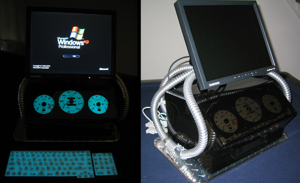
The last thing you’d expect to see adorned on a computer case is an Indiglo gauge cluster straight out of a Honda Civic…. but that is exactly what [Envador] has created. He was driving around town one evening when a car past him. The blue glow of the passing car’s dash board was extremely noticeable and caught his attention in a positive way. Any computer nerd would, of course, immediately think “hey, that would make a cool computer case“. [Envador] then set out on a mission to make it happen.

Clearly, the focus of the case is the gauge cluster. It was taken out of a Honda Civic found in a junkyard. And it just wouldn’t be cool enough to just have the gauges light up, they definitely had to display some sort of info from the computer. CPU, RAM and hard drive usage seemed like pretty good parameters to display. [Envador] expected that each of the 3 gauges would accept a pulsed signal to move the needle. After tearing down the gauge panel he found only the tachometer worked that way. The other two gauges worked by some unknown means. Instead of messing around with figuring those two out, the mechanical components of the rogue gauges were replaced with those of two aftermarket tachometers. The stock needles and indiglo backlighting were kept.

To move the now-3 tachometer needles, [Envador] used a product called PCTach that connects to the PC via serial cable. It works with accompanying software to monitor PC information and output the necessary signals to make the tachometers move according to the PC’s performance. The computer case, itself, was fabricated from smoked acrylic behind which sits the gauge cluster. A matching backlit keyboard finishes off the look nicely.

Tetris

Arduino Tetris On A Multiplexed LED Matrix

[Alex] needed a project for his microcomputer circuits class. He wanted something that would challenge him on both the electronics side of things, as well as the programming side. He ended up designing an 8 by 16 grid of LED’s that was turned into a game of Tetris.

He arranged all 128 LED’s into the grid on a piece of perfboard. All of the anodes were bent over and connected together into rows of 8 LED’s. The cathodes were bent perpendicularly and forms columns of 16 LED’s. This way, if power is applied to one row and a single column is grounded, one LED will light up at the intersection. This method only works reliably to light up a single LED at a time. With that in mind, [Alex] needed to have a very high “refresh rate” for his display. He only ever lights up one LED at a time, but he scans through the 128 LED’s so fast that persistence of vision prevents you from noticing. To the human eye, it looks like multiple LED’s are lit up simultaneously.

[Alex] planned to use an Arduino to control this display, but it doesn’t have enough outputs on its own to control all of those lights. He ended up using multiple 74138 decoder/multiplexer IC’s to control the LED’s. Since the columns have inverted outputs, he couldn’t just hook them straight up to the LED’s. Instead he had to run the signals through a set of PNP transistors to flip the logic. This setup allowed [Alex] to control all 128 LED’s with just seven bits, but it was too slow for him.

His solution was to control the multiplexers with counter IC’s. The Arduino can just increment the counter up to the appropriate LED. The Arduino then controls the state of the LED using the active high enable line from the column multiplexer chip.

[Alex] wanted more than just a static image to show off on his new display, so he programmed in a version of Tetris. The controller is just a piece of perfboard with four push buttons. He had to work out all of the programming to ensure the game ran smoothly while properly updating the screen and simultaneously reading the controller for new input. All of this ran on the Arduino.

Can’t get enough Tetris hacks? Try these on for size.

Water Tank Monitoring System Is Now Slug-Proof

[Peter] is doing his part toward protecting the environment and conserving water. He’s built a rainwater collection system complete with an underground storage tank. Since he wanted to monitor the water level in the tank, he made a level indicating system. Everything was going well until one day out of nowhere it stopped working, only returning 0’s as the level. [Peter] took a look and found that I slug had made its way into the electronics enclosure and slimed up the traces on the PCB, causing short circuits.To fix the problem [Peter] decided to redesigned the system. This time it would be built into an all-weather electrical box. The system uses a standard hobby ultrasonic range finder to measure the distance from the top of the tank to the level of the water. Two holes cut into the electrical box allow the sender/receiver components to peek outside of the enclosure. Any gaps were then filled with sealant. [Peter] also added a thermistor to measure the temperature inside the tank.The sensor values are read by an Arduino and sent wirelessly to [Peter]’s computer via a pair of XBee’s and a second Arduino with an ethernet shield. The data are sent in 3 minute intervals and automatically stored in a MySQL database for quick reference of level and temperature trends. Now [Peter] can monitor his rain water remotely and adjust his usage habits accordingly. Want to read more about water tanks? Check out this overflow monitor system.

DIY Single Pixel Digital Camera

[Artlav] wanted to build a digital camera, but CCDs are expensive and don’t respond well to all wavelengths of light. No problem, then, because with a photodiode, a few stepper motors, the obligatory Arduino, and a cardboard box, it’s pretty easy to make one from scratch.

The camera’s design is based on a camera obscura – a big box with a pinhole in one side. This is all a camera really needs as far as optics go, but then there’s the issue of digitizing the faint image projected onto the rear of the camera. That’s fine, just build a cartesian robot inside the box and throw a photodiode in there.

There are a few considerations when choosing a photodiode for a digital camera. Larger photodieodes have higher noise but lower resolution. [Artlav] has been experimenting with a few diodes, but his options are limited by export control restrictions.

Even with the right photodiode, amplifying the tiny amount of current – picoamps in some cases – is hard. The circuit is extremely sensitive to EMI, and it’s inside a box with stepper motors pulled from the scrap bin. It’s amazing this thing works at all.

Still, [Artlav] was able to get some very high resolution images across a huge range of wavelengths. He’s even getting a few images in mid-wave infrared, turning this homebrew digital camera into the slowest thermal imaging camera we’ve ever seen.

camera battery emulator

3D Printed Camera Battery Emulator

There are certainly battery hungry devices out there on the market and, unless you do some serious research before the purchase of said device, you really don’t know how it will perform. Needless to say, some of us get stuck with power hog device, and it seriously sucks because changing out batteries often is expensive and just plain annoying.

If you couldn’t tell, I am speaking from experience, my old Sony DSC-H5 camera works great with the exception of needing new batteries every hour. And if you get cheap batteries, the camera won’t even turn on! There’s a USB connector on the camera but it is only for transferring data and there is also no DC input jack. The entire situation is a totally bummer.

I’m happy (or disappointed) that I am not alone in the world. [Phil] wrote into the HaD tip line to tell us about his solution to this very problem. He has a Canon SD1000 camera and although the battery works fine he needs it to work at an altitude of 15km in order to take some sunrise photos. Cold weather testing (in the fridge freezer) showed that the battery isn’t going to cut the mustard for the hour-long flight. The rest of the balloon-lifted unit already has a battery pack and the plan would be to tap into that to power the camera. Unfortunately his camera, like mine, doesn’t have a DC input jack and can not be powered off the USB port.

[Phil] decided to make a 3D printed battery emulator. It sits in place of the stock battery and holds bare wire where the batteries terminals normally are. The other end of the wires are run out of the camera to a voltage regulator that converts the battery pack’s 6 volts down to the 3.9 that the camera needs.

Continue reading “3D Printed Camera Battery Emulator”

Tweakie CNC Router

Home Made CNC Router Boasts Welded Steel Frame And Super Tidy Wire Management

[Cooperman] had been poking around the ‘net checking out DIY CNC machines for a while. He wanted to build one. During his search, he noticed that there was a common thread amongst homemade machines; they were usually made from parts that were on hand or easily obtainable. He had some parts kicking around and decided to hop on the band wagon and build a CNC Router. What sets [Cooperman]’s project apart from the rest is that he apparently had some really nice components available in his parts bin. The machine is nicknamed ‘Tweakie‘ because it will never really be finished, there’s always something to tweak to make it better.

The foundation for Tweakie is a welded frame made from 25mm steel square tubing. A keen observer may point out that welding a frame may cause some distortion and warping. [Cooperman] thought of that too so he attached aluminum spacers to the steel frame and lapped them flat. After that, fully supported THK linear bearings were attached to the now-straight spacer surface. Both the X and Y axes have ball-screws to minimize backlash and are powered by NEMA23 stepper motors. The Z axis uses 16mm un-supported rods with pillow block linear bearings. Unlike the X and Y, the Z axis uses a trapezoidal lead screw and bronze nut. [Cooperman] plans on replacing this with a ball-screw in the future but didn’t have one on hand at the time of assembly.

Mach3 is the software being used to control the CNC Router. It communicates via parallel port with a 3-axis StepMaster motor driver board that can handle providing 24vdc to the stepper motors. All of the electronics are mounted neatly in an electrical cabinet mounted on the back of the machine. Overall, this is a super sturdy and accurate machine build. [Cooperman] has successfully cut wood, plastic and even aluminum!