[Sefi Attias] just sent us a heartwarming little video of how he proposed to his girlfriend [Tania] — using a little help from technology and other makers.
As a maker, [Sefi] was always building things which impressed [Tania], so he thought it was only fitting to make the proposal a one-of-a-kind maker experience.
He started by designing the engagement ring himself, to be 3D printed. It’s an amazingly complex little thing made up of the repeating words of the quote “I will betroth you to me forever”. It was almost too complex in order to print — but they managed to do it in wax, which allowed them to create a mold and then cast the final part in white gold. Once complete, they set a diamond in place to cap it all off.
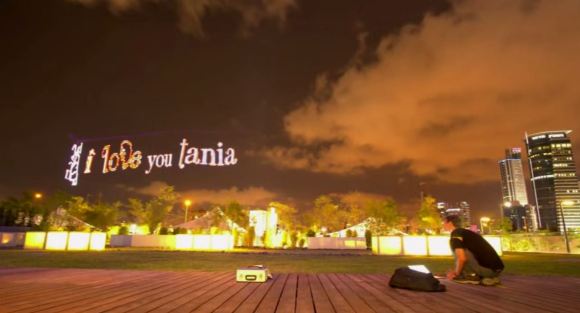
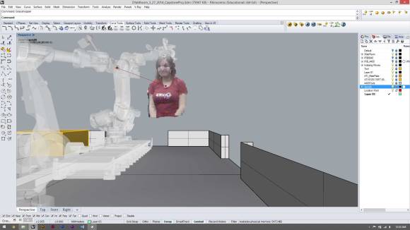
The second step was the proposal, which was made possible using a quadrotor, a strip of RGB LEDs, and a long camera exposure. To show it off in real-time to [Tania] they setup a projector and screen on the side of the street, providing a surreal window into the park behind them. It was all made possible with the help from over 20 people from the XLN Makerspace and SkyLens (the quadrotor people).
Oh yeah, and she said yes.
 We’re doing something new. We’ve asked [Chris Gammell] to take over our Twitter account (