![]()
Cheap FPGA boards are readily available, as are VHDL implementations of classic CPUs like the 6502, 6809, and Z80. Up until now, we haven’t seen anyone take these two parts and combine them into a complete system that turns an FPGA board into a complete 8-bit retrocomputer. Thanks to [Grant]’s work, it’s now possible to do just that (server on fire, here’s a google cache) with a $30 FPGA board and a handful of parts.
In its full configuration, the Multicomp, as [Grant] calls his project, includes either a 6502, 6809, Z80, or (in the future) a 6800 CPU. Video options include either monochrome RCA, RGB VGA, or RGB via SCART. This, along an SD card interface, a PS2 keyboard, and the ability to connect an external 128kB RAM chip (64k available) means it’s a piece of cake to build a proper and complete portable retrocomputer.
What’s extremely interesting about [Grant]’s project is the fact the data and address lines are fully exposed on the FPGA board. This means it’s possible to add whatever circuit you’d like to whatever retrocomputer you can imagine; if you want a few NES gamepads, an IDE interface, or you’d like to design your own primitive video card, it’s just a matter of designing a circuit and writing some assembly.
If you’d like to build your own, search “EP2C5T144C8N” on the usual sites, grab a few resistors and connectors, and take a look at [Grant]’s documentation and upcoming examples.
Via 6502.org forums
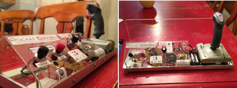 Like a lot of parents, [justbennett]’s kids like to play rocket and spaceship command. His kids’ imagination-assigned controls kept shifting from this LEGO to that banana to the dog’s tail, so [justbennett] did what he had to do: make