C++ Reverbs From A Matlab Design

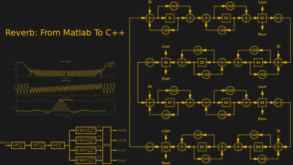
The guitar ‘Toing’ sound from the ’70s was epic, and for the first time listener it was enough to get a bunch of people hooked to the likes of Aerosmith. Reverb units were all the rage back then, and for his DSP class project, [nebk] creates a reverb filter using Matlab and ports it to C++.

Digital reverb was introduced around the 1960s by Manfred Schroeder and Ben Logan. The system consists of essentially all pass filters that simply add a delay element to the input signal and by clubbing a bunch together and then feeding them to a mixer. The output is then that echoing ‘toing’ that made the ’80s love the guitar so much. [Nebk]’s take on it enlists the help of the Raspberry Pi and C++ to implement the very same thing.

In his writeup, [nebk] goes through the explaining the essentials of a filter implementation in the digital domain and how the cascaded delay units accumulate the delay to become a better sounding system. He also goes on to add an FIR low pass filter to cut off the ringing which was consequent of adding a feedback loop. [nebk] uses Matlab’s filter generation tool for the LP filter which he includes the code for. After testing the design in Simulink, he moves to writing the whole thing in C++ complete with the filter classes that allows reading of audio files and then spitting out ‘reverbed’ audio files out.

The best thing about this project is the fact that [nebk] creates filter class templates for others to play with. It allows those who are playing/working with Matlab to transition to the C++ side with a learning curve that is not as steep as the Himalayas. The project has a lot to learn from and is great for beginners to get their feet wet. The code is available on [GitHub] for those who want to give it a shot and if you are just interested in audio effects on the cheap, be sure to check out the Ikea Reverb Plate that is big and looks awesome.

Inductance In PCB Layout: The Good, The Bad, And The Fugly

When current flows through a conductor it becomes an inductor, when there is an inductor there is an electromagnetic field (EM). This can cause a variety of issues during PCB layout if you don’t plan properly, and sometimes we get burned even when we think we have planned for unwanted inductance and the effects that come with them.

When doing high speed logic we need to be able to deliver sudden changes in current to the devices if we want to have proper switching times and logic levels. Unfortunately inductance is usually not a friend in these circumstances as it resists those sudden changes in current. If the high speed devices are driving capacitive loads, which themselves are resisting changes in voltage, even more instantaneous current is needed.

Simply put, inductors resist a change of current, and can act as a low pass filter when in series with the signal or power supply flow. Inductors do this by storing energy in the flux surrounding the conductor. Alternatively capacitors resist a change in voltage (again by storing energy) and can act as a high pass filter when in series with the signal. This makes them a valuable tool in the fight against unwanted inductance in power supply distribution.

In the video below, and the remainder of this article, I’m going to dive into the concept of inductance and how it affects our design choices when laying out circuit boards.

Continue reading “Inductance In PCB Layout: The Good, The Bad, And The Fugly”

Circuit VR: Oscillating Bridges

Circuit VR is where we talk about a circuit and examine how it works in simulation with LT Spice. This time we are looking at a common low-frequency oscillator known as the Wien bridge oscillator.

What makes an oscillator oscillate? A circuit with amplification that gets the same amount of the output signal fed back into its input, in phase, will oscillate. This is the Barkhausen criterion. Here, we’re going to look into what makes an oscillator work in simulation, and gain some insight into what happens when there’s too much feedback and too little.

In particular, we’ll look at the Wien bridge oscillator, a very simple design that originated as a way to measure impedance back in 1891. Modern versions add some additional features, but let’s start with the most simple implementation and work our way up.

Continue reading “Circuit VR: Oscillating Bridges”

x86 emulation running DOS on ESP8266

PC-XT Emulator On ESP8266

Do you remember the simpler times when you had a DOS command line, a handful of commands, and you talked to the hardware through a few BIOS and DOS interrupts? Okay, maybe it was a little limited, but nostalgia doesn’t care. Now [mcuhacker] is working on bringing some of those memories back by getting a PC-XT emulator running on an ESP8266.

For the x86 CPU emulator, he ported Fake86 which is written in C, and created an Arduino IDE environment for it. The MS-DOS 3.3 bootdisk image is stored in flash and is accessed as the A: drive. There’s no keyboard yet but he has 640×200 CGA working with 80×25 characters on a 3.5″ TFT display with the help of a low pass filter circuit. In the video below he shows it booting to the point where it asks for the date.

Continue reading “PC-XT Emulator On ESP8266”

If The I And Q Of Software Defined Radio Are Your Nemesis, Read On

For those of us whose interests lie in radio, encountering our first software defined radio must have universally seemed like a miracle. Here is a surprisingly simple device, essentially a clever mixer and a set of analogue-to-digital or digital-to-analogue converters, that can import all the complex and tricky-to-set-up parts of a traditional radio to a computer, in which all signal procession can be done using software.

A quadrature mixer. Jugandi (Public domain).

When your curiosity gets the better of you and you start to peer into the workings of a software defined radio though, you encounter something you won’t have seen before in a traditional radio. There are two mixers fed by a two local oscillators on the same frequency but with a 90 degree phase shift, and in a receiver the resulting mixer products are fed into two separate ADCs. You encounter the letters I and Q in relation to these two signal paths, and wonder what on earth all that means.

Continue reading “If The I And Q Of Software Defined Radio Are Your Nemesis, Read On”

Scope Review: Keysight 1000 X-Series

A few weeks ago we published an article on the newly released Keysight 1000X, an oscilloscope that marks Keysight’s late but welcome entry into the hacker-centric entry-level market. Understandably, this scope is causing a lot of excitement as it promises to bring some of the high-end pedigree of the well-known 2000X and 3000X models down to a much affordable price. Now couple that with the possibility of hacking its bandwidth lock and all this fuss is well justified.

[Dave Jones] from the EEVblog got his hands on one, and while conducting a UART dump saw the scope report 200 MHz bandwidth despite being labelled as a 100 MHz model. He then proceeded to actually hack the main board to unlock an undocumented 200 MHz bandwidth mode. This created a lot of confusion: some said [Dave] got a “pre-hacked” version, others assumed all 100 MHz versions actually have a stock bandwidth of 200 MHz.

Alongside the question of bandwidth, many wondered how this would fare against the present entry-level standard, the Rigol 1054Z. Is the additional cost and fewer channels worth the Keysight badge?

Keysight’s response to our queries and confusion was the promise to send us a review unit. Well, after receiving it and playing around with it, clearly a lot of Keysight’s high-end excellence has trickled down to this lower end version. However, this machine was not without some silly firmware issues and damning system crashes! Read on the full review below. Continue reading “Scope Review: Keysight 1000 X-Series”

A Mess Of Wires Turned Into An Analog Synth

Over on YouTube, [GumpherDM3] built one of the greatest musical projects we’ve seen in a long time. It’s an analog synthesizer that is one of a kind. It’s going to stay one of a kind, too: no one would ever want to copy this mess of wires and perfboard that was successfully turned into a complete musical instrument.

The design of this synth is what you would expect from something that draws its inspiration from semimodular synths such as the Minimoog and Korg MS20. There are four VCOs on this synth, two audio and two used for the LFOs. A four-pole low pass filter, VCA, and two envelope generators round out the purely analog portion of the build. There’s an arpeggiator in there too, which makes for a really great demo video (below).

Inside, this is a true analog synth with the VCOs, filter, and VCA built around the LM13700 transconductance amplifier. The build log shows these chips spread out around half a dozen breadboards before being plugged into sockets soldered to handwired perf board. This synth is a one of a kind instrument – no one would want to build this thing twice.

Additional features include an Arduino with a MIDI in port sending out CV signals to the analog part of the synth. This thing has everything you would expect from a modern take on an analog synthesizer, and it sounds good, too.

Continue reading “A Mess Of Wires Turned Into An Analog Synth”