Adafruit Interviews The CEO Of FTDI

When it comes to electronic hobbyists and EEs, there is no company that deserves a few raised eyebrows than FTDI. They made their name with USB converter chips, namely USB to serial chips that are still very popular today. So popular, in fact, that clones of these chips are frequently found in the $2 Arduinos from China, and other very low-cost devices. A little more than a year ago, a few clever people noticed FTDI drivers were bricking these counterfeit chips by setting the USB PID to 0000. The Internet reacted to this move and FTDI quickly backed down from that position. The Windows driver was fixed, for about a year until the same shenanigans were found again.

Adafruit recently sat down with [Fred Dart], CEO of FTDI, giving us all the first facts and figures that aren’t from people frustrated with Windows’ automatically updated drivers. The most interesting information from [Fred Dart] is how FTDI first found these counterfeit chips, what FTDI chips are being counterfeited, and how many different companies are copying these chips.

The company first realized they were being cloned when they couldn’t reproduce results of a Chinese-made ‘FTDI’ USB to RS232 cable that behaved strangely. A sample of the cables were shipped to FTDI and after inspecting the chip inside, FTDI found it was a clone with a significantly different architecture than a genuine chip.

So far, the counterfeiters appear to only be counterfeiting the SSOP version of the FT232RL and occasionally the older FT232BL chip. From what FTDI has seen, there appears to be only one or two companies counterfeiting chips.

As the CEO of FTDI, [Fred] has a few insights into what can be done to stop counterfeiters in China. The most important is to trademark the logo. This isn’t just the logo for a webpage, but one that can be laser etched onto the plastic package of the chip. US Customs has been very amenable to identifying counterfeit components, and this has led to several shipments being destroyed. Legal action, however, is a bit hard in China, and FTDI is dealing with a gang that counterfeits more than FTDI chips; there’s a high likelihood this gang was responsible for the fake Prolific PL23o3 chips a few years ago.

As far as FTDI bricking counterfeit chips is concerned, [Fred Dart] wasn’t silent on the issue, he merely wasn’t asked the question and didn’t bring it up himself.

ARMing A Breadboard — Everyone Should Program An ARM

I’m always a little surprised that we don’t see more ARM-based projects. Of course, we do see some, but the volume isn’t what I’d expect given that low-level ARM chips are cheap, capable, low power, and readily available. Having a 32-bit processor with lots of memory running at 40 or 50 MIPS is a game changer compared to, say, a traditional Arduino (and, yes, the Arduino Due and Zero are ARM-based, so you can still stay with Arduino, if that’s what you want).

A few things might inhibit an Arduino, AVR, or PIC user from making the leap. For one thing, most ARM chips use 3.3V I/O instead of the traditional 5V levels (there are exceptions, like the Kinetis E). There was a time when the toolchain was difficult to set up, although this is largely not a problem anymore. But perhaps the largest hurdle is that most of the chips are surface mount devices.

Of course, builders today are getting pretty used to surface mount devices and you can also get evaluation boards pretty cheaply, too. But in some situations–for example, in classrooms–it is very attractive to have a chip that is directly mountable on a common breadboard. Even if you don’t mind using a development board, you may want to use the IC directly in a final version of a project and some people still prefer working with through hole components.

The 28 Pin Solution

One solution that addresses most, if not all, of these concerns is the LPC1114FN28 processor. Unlike most other ARM processors, this one comes in a 28 pin DIP package and works great on a breadboard. It does require 3.3V, but it is 5V tolerant on digital inputs (and, of course, a 3.3V output is usually fine for driving a 5V input). The chip will work with mbed or other ARM tools and after prototyping, you can always move to a surface mount device for production, if you like. Even if you are buying just one, you should be able to find the device for under $6.

Continue reading “ARMing A Breadboard — Everyone Should Program An ARM”

Serial Surgery Saves Wacom Tablet From Landfill

Years ago, [Greg] got a Wacom Artpad II graphics tablet through Freecycle. What’s the catch, you ask? The stylus was long gone. When he found out how expensive a direct replacement would be, the tablet was laid to rest in his spare parts box. Fast forward a few years to the era of the phone-tablet hybrid and [Greg]’s subsequent realization that some of them use Wacom stylii. Eight bucks later, he’s in business, except that the tablet is serial. Wacom no longer supports serial tablets, so he had to convert it to USB.

With the help of the WaxBee project and a Teensy 2.0, he would be able to emulate an Intuous2 tablet by sniffing and re-encoding the packets.  Things got a little hairy when he went under the hood to remove the ADM202 TTL-to-RS232 chip with a Dremel—he accidentally gouged some of the pads it sat on as well as a few of the traces. Feeling frustrated, [Greg] took some high-res pictures of the board and posted them to a message board. As it turns out, those pictures helped him recreate the traces and get the tablet running. A little big of glue and tape later, he was in business. [Greg] even gave himself access to reprogram the Teensy.

Hacking A DVD Recorder

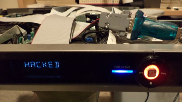
Hacked DVD Recorder

[w00fer] wanted to see if any modifications to a DVD Recorder were possible. Initially, the goal was to upgrade the internal hard drive for additional storage. However, after cracking open a DVDR3570H and finding a service port, he decided to look a bit deeper.

Connecting an RS232 to USB converter to the service port resulted in garbled data. It turned out that the port was using TTL signal levels instead of RS232 levels. This was solved by building a converter using the MAX232 converter IC.

With the converter in place, the service menu appeared. It performs some tests and spits out the results when the device is booted. After that, it sits at a prompt and waits for commands. Fortunately, [w00fer] found the service manual which lists the available commands. So far, he’s been able to generate test patterns, test lights, change the display text, spin up the hard drive, and read device information. However, the next steps include disabling Macrovision copy protection, dumping the EEPROM and NVRAM, and copying data off of the hard drive. If you think you can help [w00fer] out, let him know.

Connecting An Old Scope To A Computer

Scope

A friend of [Michael]’s said his company was getting rid of some old lab equipment and asked him if he wanted a very large and very old digital storage oscilloscope. A ‘hell yes’ and we’re sure a few beers later, [Michael] found an old Gould 200 MHz four-channel scope on his bench. Even 20 years after its production it’s still a capable tool, but the serial ports on the back got [Michael] wondering – would it be possible to plot the screen of the scope on his computer?

The scope has three ports on the back – GPIB, miscellaneous I/O, and RS423. The latter of those ports is similar enough to RS232 that a USB to Serial converter just might work, and with the help of a null modem cable and a terminal, [Michael] was able to connect to this ancient scope.

In the manual, [Michael] found a the serial commands for this scope. The most useful of these is a command that prints out the contents of the scope’s trace memory as a series of 1-byte integers. With a short bit of PERL programming, [Michael] can create a PDF plot of whatever is on the scope’s screen. It’s formatted perfectly for Gnuplot, MATLAB, or even Excel.

Awesome work, and especially useful given these old scopes are slowly making their way to a technological boneyard somewhere.

Adding EPaper Navigation Data To A Sailboat

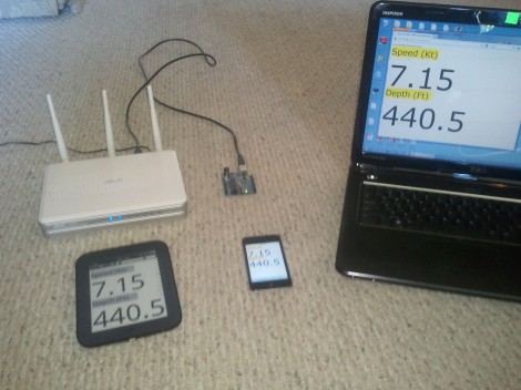
[Mike Holden] has been on the hunt for a display that is easy to read in bright sunlight. He wants to use it to read out navigational data on his sail boat. The best option is an ePaper display. He managed to build a system that will feed updating NMEA 0183 data to a Nook Simple Touch.

NMEA 0183 is a protocol that governs data from marine navigational equipment. The most obvious is GPS, but there are a lot of possibilities like sonar, a gyrocompass, and an autopilot. To get things rolling he wrote an Arduino sketch which generates dummy packets using the standard. This let him develop and test the system without being near any of the real equipment. The heart of the build is a WiFi router. It pulls in the data over a USB port using an RS232 to USB converter cable. A Python script parses the data and generates a webpage which refreshes the data every second. This is loaded using Opera browser on the Nook

Check out the video after the break to see a demo of the system.

Continue reading “Adding EPaper Navigation Data To A Sailboat”

IR Remote As PC Input

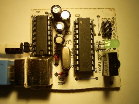
As a learning experience [GeriBoss] put together an IR remote control receiver board for his PC. His want of volume control from across the room was reason enough to undertake the project, and he got to work with a 38 kHz receiver module and Manchester encoding in the process.

The decoder portion of the project is built around an ATtiny2313 chip. The external interrupt pin (INT0) is connected to a TSOP31238. When it decodes a valid remote code it pushes a character to the RS232 chip connecting to the computer’s serial port.

We think this is a wonderful accomplishment for [GeriBoss], but we encourage him to refine the design further. You’ll notice in the image there’s a USB port on the board which is only used to provide regulated power. We know it’s possible to use V-USB with the ATtiny2313 to add USB functionality and this would be a great way to learn about it. We’d also like to mention the resistor and capacitor suggested for filtering the IR receiver module signal. We’ve included the recommended application schematic for that part after the break.

Continue reading “IR Remote As PC Input”