
Most RC planes follow a simple control scheme: elevators for pitch, rudder for yaw, and ailerons for roll. This one-to-one mapping keeps things straightforward, and fewer actuators means less weight. But nature has other ideas. Birds achieve flight control through complex, coordinated movements where different body parts can affect multiple degrees of freedom simultaneously. Now, researchers at EPFL have brought this biological approach to robotics with the LisEagle, a drone featuring morphing wings and tail that demonstrate remarkable stability.
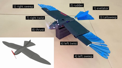
The LisEagle packs seven different actuation methods alongside its nose-mounted motor. Three of these control the bird-like wingtips and spreading tail, while the remaining actuators handle more conventional controls: independently twisting wing bases (similar to ailerons) and a tail assembly that combines elevator and rudder functions in its vertical stabilizer.
Testing took place in controlled indoor conditions, with the maintaining position in front of an open wind tunnel. Optical position tracking provided closed-loop feedback and power was provided via a tether to minimize weight. A PID flight controller orchestrated all seven actuators in concert, achieving impressive stability even when faced with induced turbulence or being poked with a stick. In a demonstration of redundancy, the researchers deliberately disabled the twisting wing mechanisms, and the aircraft maintained control using just its wingtips and tail.
The team went further, employing Bayesian optimization to find the most efficient actuator combinations. This revealed potential energy savings of up to 11%, with optimal configurations varying based on airspeed as lift requirements changed.
While research into the flight mechanisms of bees, bats and birds might not immediately translate to practical applications, it deepens our understanding of flight control principles. Don’t be surprised if morphing wings become a more common sight in future aircraft designs.


