Building A Bipolar Supply From A Boost Converter

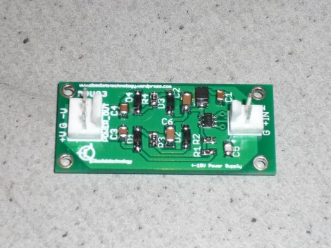
This DC-DC Bipolar PSU was developed for use with a guitar effects pedal. [Obsolete Technology] needed to source both positive and negative 15V. This is pretty easy to do if you’re converting from mains, but he wanted a solution that could work with a lower-voltage AC/DC wall wort or even from batteries.

The part that pulls it all together is the LT3467. It’s a switching power regulator which offers a range of features configured by the layout of a handful of external passive components. It can put out 80 mA on each line (positive and negative). Also extremely useful for this application is the chip’s high frequency operation. Depending on the version, it switches at 1.3 or 2.1 MHz. This is high enough that it will not introduce audible noise into the audio system.

We’ve got an exercise bike whose negative supply for the LCD is blown. We’re going to try build this circuit, trimming it for our voltage needs, and get the contrast working again.

[Thanks Olli]
Measuring SMD Parts With A Home Brew Version Of Smart Tweezers

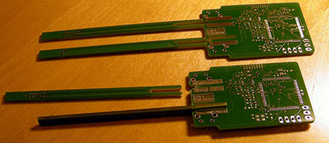
SMD parts are great; they allow you to pack more parts on a board, do away with drilling dozens of PCBs, and when done correctly can produce a factory-quality board made in a home lab. There’s one problem with SMD parts; troubleshooting and measuring them. The ideal solution would be something akin to the Smart Tweezers we’ve seen before, but this fabulous tool costs three hundred bones. [Kai] came up with a much cheaper solution: home brew smart tweezers that can be built for a tenth of the cost as the professional model.

What [Kai] built is an LCR meter, basically a tool that measures inductance, capacitance, and resistance in a very, very small form factor. The technique of measuring a part’s properties involves feeding a set frequency into the device and measuring the phase, voltage and current coming out. It’s all wonderfully explained by [Dave] over at EEVblog in one of his earlier videos.

The hardware [Kai] is using includes an LCD display from a Nokia phone, an MSP430-based microcontroller, a very tiny opamp near the tip of one of the points of the tweezer, and a programmable gain amplifier used to measure the components. In testing, [Kai] can measure very low-value components with a +/- 2% accuracy, and larger, more realistic components with +/- 0.25% accuracy. An awesome accomplishment, and much better than the common Chinese meters that can’t measure in the nH/pF/mΩ range.

[Kai] hasn’t gotten his pair of smart tweezers working yet – he still needs to get the circuit up and running and write some software. We’ll keep our readers apprised of [Kai]’s progress, though, and gently convince him to work with Seeed Studio or someone similar to get his version of Smart Tweezers onto maker’s workbenches the world over.

Nyan Cat Built Into The Wall Of A House

You’re going to need your best negotiating skills if you want to convince your significant other to let you add your own Nyan Cat to the kids’ room. This goes a bit deeper than just mounting something on the wall. The LEDs which light up this Nyan Cat installation are actually in the wallboard itself.

Luckily, this is actually a ‘playground for grown-up kids’. [Schinken] and his fellow hackerspace members built it at their location in Bamberg, Germany. It started as a Nyan Cat scarf, which was easy enough to hang on the wall. To make it sparkle they added sixteen LEDs. But you won’t see the wires from either side. A hole was drilled at the location of each diode, with a trench chiseled between them. This makes room for the wires, and was covered with spackle before painting. It turned out to be a pretty simple way to add a focal point to the room, and it certainly has the appropriate level of geekiness for a hackerspace.

Developing With EBay-sourced ARM + LCD Dev Boards

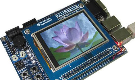
eBay isn’t only about counterfeit designer handbags and boxes of all-marshmallow Lucky Charms, sometimes there’s actually something useful for sale. [Matt] found a bunch of Chinese-made ARM development boards with integrated LCD displays on the ‘bay, but without a reliable toolchain, these boards – as cool as they are – are nearly useless. Thankfully, he figured out how to do something with these boards, and neatly packaged everything into a VirtualBox image.

The boards in question usually include a 2.4″ or 3.2″ touch panel LCD, an STM32F103 ARM Cortex-M3 CPU, a microSD card connector, and sometimes a few other goodies like 16MB of Flash memory and an RS-232 port. An amazing amount of computational capability packaged into an easy-to-use form factor made even more awesome by their $40 price point.

Because these boards offer so much more than a common Arduino, a proper OS is in order. [Matt] looked over FreeRTOS and included a few demo programs for his Ubuntu-based VirtualBox image (available for download on [Matt]’s site, it’s a dropbox, email us if you need some hosting, [Matt]) Never mind, see below.

Programming these boards can be done over a serial interface, but a JTAG programmer such as a Bus Blaster makes things very, very easy.

You can check out a few demos [Matt] put together after the break. It’s a very cool development that is much more suited for being integrated into an electronics project than a Raspberry Pi or other such high-power ARM board, and something we hope to see more of in the future.

EDIT: You know what’s really good for hosting Linux distros? Torrents. That’s [Matt]’s distro and the HaD crew is seeding. Please seed.

Continue reading “Developing With EBay-sourced ARM + LCD Dev Boards”

Do Not Look Into 12 Watt UV Lamp With Remaining Eye

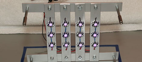
We’ve seen a couple of UV lamp builds for exposing photosensitive PCBs and erasing EPROMs, but [John] over at pcboard.ca decided if it’s worth doing, it’s worth overdoing. They designed a UV exposure board using twelve 1 Watt UV LEDs, an impressive amount ultraviolet light that you probably shouldn’t look at for too long.

We’ve seen UV exposure boxes before, usually made with a bunch of 5mm UV LEDs soldered to a piece of protoboard. These projects do their job, but the exposure time is on the order of minutes. The PCboard.ca UV lamp can expose a PCB in just 20 seconds.

The build began with four pieces of aluminum bar, 1 inch wide and 1/8″ thick. The 12 star LEDs were glued down to this bar with thermal adhesive and serve their purpose as a rather large heat sink.

[John] performed a little test to determine how long it would take this monstrous UV source to expose a PCB. By copying a PCB mask four times and placing it over an unexposed board, [John] made a PCB with exposure times of 60, 45, 30, and 15 seconds. After developing and etching, all but the 15-second exposure was fully etched, an amazing result that will probably lead to some very, very rapid prototyping.

All the more impressive is the fact that only four 1-watt LED drivers were used for this build. That’s right, this UV lamp is actually operating at about a quarter of its maximum rating, or about 285mA per LED. We’d hate to see this thing operate at full power, protective eyewear or not.

Atari Punk Stick Puts A Synth In A Joystick

[youtube=http://www.youtube.com/watch?v=ngXrTd-8jf4&w=470]

The Atari Punk Console, a tiny synthesizer based on the ubiquitous 555 timer chip, is the first build de rigueur for any budding electronic wizard wanting to build musical devices. With just a handful of caps, resistors, and a pair of pots, the APC is a fabulously fun and easy build made even cooler by [Pat]’s addition of a joystick.

The circuit of the Atari Punk Console consists of a 556 chip – basically two 555s put into the same package – and a pair of potentiometers to control the frequency and output of this very basic synth. Since most joysticks are just two pots arranged on an X-Y mount, [Pat] thought it would be cool to control his APC without twiddling knobs, and instead sweeping a joystick around.

After acquiring an old Microsoft joystick from his local Goodwill, [Pat] wired up his Atari Punk Console to the joystick, using the ‘fire’ button to turn the output on and off. The result is everything between a low machine gun-like tone to a nasal square wave that will hopefully keep pace with your chip-based audiophile friends.

Continue reading “Atari Punk Stick Puts A Synth In A Joystick”

Upverter 2.0 Launches

Disclosure: I currently work at Upverter

We’ve featured Upverter here in the past. At that time, the EDA tool was capable of collaborative schematic capture. Today, Upverter is launching version 2.0 of their tool which includes many new features allowing for end-to-end electronics design.

Upverter now has a PCB editor, allowing you to manufacture your designs. They are working with PCB manufacturers to make it easy to choose a fab and submit design files. Other new features include a Spice based simulation engine allowing in-browser simulation, and product lifecycle management features to help manage your project’s bill of materials.

When we last looked at Upverter, it was just a tool for creating and sharing schematics. With today’s launch, the tool can be used for designing electronics from start to finish. Since Upverter is free for open source projects, it will be interesting to see how hackers use it.

You can check out a tour of the new features. Any thoughts on using a cloud based EDA tool? Let us know in the comments.