Some of the neatest products are made from the byproducts of other industries. Take petroleum jelly, for example. Its inventor, Robert Chesebrough, a chemist from New York, came upon his idea while visiting the oil fields of Titusville, Pennsylvania in 1859. It took him ten years to perfect his formula, but the product has been a household staple ever since. Chesebrough so believed in Vaseline that he ingested a spoonful of it every day, and attributed his 96-year longevity to doing so.
Well, some byproducts can simply be beautiful, or at least interesting. On that note, welcome to a new series called Boss Byproducts. We recently ran an article about a laser-engraved painting technique that is similar to the production of Fordite. I had never heard of Fordite, but as soon as I found out what it was, I had to have some. So, here we go!
The chiptune scene is dominated by Game Boys and other Nintendo hardware, but one should never forget the gorgeous, beautiful tones that come from the hallowed Commodore 64. [Linus Åkesson] knows this well, and it’s at the heart of his work on the Commodordion. Now, he’s built an even better version.
The original idea he had was to build an accordion-like control surface for the SID chip in a Commodore 64. The device is capable of creating beautiful accordion-like music with a simple 8-bit flair. He has since dubbed the original Commodordion the “bass Commodordion,” while the new version is classified as a tenor instrument.
The prime upgrades are ergonomic. The previous instrument was too heavy, with the left hand having to carry an entire Commodore 64 on its own. It was also hard to reach the keys. The new version is much lighter, with one of the two C64s of the original having been removed. The supporting electronics have been redesigned to more neatly fit into a space behind the bellows.
The result is a machine that’s far easier to play, and one that won’t injure the user in extended play sessions. “It’s now a pleasure, not a pain,” says [Linus]. The payoff in usability is obvious, and the tunes themselves are hauntingly beautiful.
Usually, when you need to sense something in a project, the answers are straightforward. Want to sense air temperature? There’s a sensor for that. Particulate content in the air? There’s a sensor for that, too. Someone sneaking up on you? Get yourself some passive infrared sensors (PIRs) and maybe a smart camera just to be sure.
But sometimes you can be sneaky instead, saving the cost of a sensor by using alternative techniques. Perhaps there’s a way to use the hardware you already have to determine what you need. Maybe you can use statistical methods to calculate the quantity you’re looking for from other measurements.
Today, we’ll examine a great example of a “pseudo-sensor” build in an existing commercial device, and examine how these techniques are often put to good use in industry.
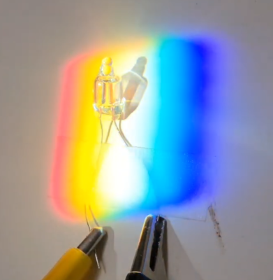
Neon lamps are fun to play with. These old-school indicators were once heavily utilized in many types of equipment for indication purposes but now seem largely relegated to mains voltage indication duties. Here’s a fun video by [Ashish Derhgawen], discussing the photoelectric effect of neon lamps with some simple demonstrations.
Orange light makes it light!
[Ashish] demonstrates the well-known photoelectric effect by triggering a sub-biased neon lamp with visible light from an LED. Neon bulbs work on the principle of voltage-induced ionization, creating a visible glowing plasma. If the applied voltage is high enough, around 60 to 80 V, electrons get knocked off the neutral neon atoms. The now free electrons, roaming around highly energized, will eventually come across a neon ion (missing an electron) and recombine to make it neutral again.
The results are a lower total energy state, and the difference in energy is resolved by the emission of a photon of light, which, in the case of neon, is a dull reddish-orange. Nothing unusual there. However, nothing will happen if the applied voltage bias is just below this device-specific threshold. There’s not enough energy to strip electrons.
Apply an external light source, and this threshold can be exceeded. The photons from the LED are just energetic enough to strip a small number of electrons from the surface of the electrodes, and this causes a cascade, or avalanche effect, lighting up the plasma and turning on the neon lamp. Take away the external light source, and it dies down and goes dark.
Magnetic levitation has not quite revolutionized the world of transit the way some of us might have hoped. It has, however, proven useful to [mrdiytechmagic], who has put the technology to grand use in making his levitating snail lamp.
The build is actually relatively complicated compared to some levitating toys you might have seen before. It uses a number of coils to produce a magnetic field to levitate the 3D printed plastic snail which contains the lighting element itself.
The actively controlled levitation base uses a magnetic sensor to detect the changing field as the snail moves above it. It then varies the current going to the various coils to keep the snail balanced and in place. Power is transmitted with a further larger coil, much as in a wireless phone charger. This is picked up by a circuit in the snail, and used to power the LEDs inside.
It might not have been our first choice, but having seen it in action, we can’t deny a levitating 3D printed snail is pretty impressive. If you’d prefer something slightly more befitting such a high-tech looking presentation, perhaps a hovering SpaceX Starship would be more your speed.
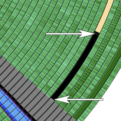
[GloriousCow] has started working on a series of investigations into the various historical floppy disk copy protection schemes used in the early days of the IBM PC and is here with the first of these results, specifically Formaster’s Copy-Lock.
This is the starting sector of track 6. It looks empty, but it’s not quite.
The game in question is King’s Quest by Sierra Entertainment, which used a ‘booter disk’ with the Copy-Lock protection scheme. Instead of having to boot DOS separately, you could just insert this disk and the game would launch automatically. Early copy protections often used simple methods, like adding sectors with non-standard sizes or tampering with sector CRC values to create disk errors. Copy-Lock employed several such tricks together, making it challenging for standard floppy disk hardware to replicate. In the case of Copy-Lock, Sector 1 on track 6 was intentionally written as only 256 bytes, with a 256-byte blank section to fill the gap. Additionally, the CRC was also altered to add another layer of protection.
When attempting to read the disk, the PC BIOS interrupt routine assumes it’s looking for a standard 512-byte sector, so when a “read sector” command is issued to locate the sector, it never finds it. To detect a dodgy copy, the game bypasses the BIOS and talks directly to the floppy disk controller using some custom code. The first part of the code uses the standard INT 13h routine to seek to track 6, sector 1, where it expects a fail since there is no valid sector there. Next, the floppy controller sends the “read track” command to perform a raw dump of all 512 bytes at this address and looks for a magic number, 0xF7, sitting in the final byte. That empty second half of the short sector is indeed not empty and is the check the game makes to determine if it was written with the Copy-Lock capable hardware. That last point is pertinent; you can’t create this disk structure with a standard IBM PC floppy disk controller; you need specialized hardware that can write different-sized sectors and incorrect CRCs, and that costs money to acquire.
We recently covered the copy protection scheme used for Dungeon Master on the Atari ST and the Amiga. If you’re thinking less about how a floppy got cracked and copied and more about how to preserve these digital relics, check this out!
DEC’s LAN Bridge 100 was a major milestone in the history of Ethernet which made it a viable option for the ever-growing LANs of yesteryear and today. Its history is also the topic of a recent video by [The Serial Port], in which [Mark] covers the development history of this device. We previously covered the LANBridge 100 Ethernet bridge and what it meant as Ethernet saw itself forced to scale from a shared medium (ether) to a star topology featuring network bridges and switches.
Featured in the video is also an interview with [John Reed], a field service network technician who worked at DEC from 1980 to 1998. He demonstrates what the world was like with early Ethernet, with thicknet coax (10BASE5) requiring a rather enjoyable way to crimp on connectors. Even with the relatively sluggish 10 Mbit of thicknet Ethernet, adding an Ethernet store and forward bridge in between two of these networks required significant amounts of processing power due to the sheer number of packets, but the beefy Motorola 68k CPU was up to the task.
To prevent issues with loops in the network, the spanning tree algorithm was developed and implemented, forming the foundations of the modern-day Ethernet LANs, as demonstrated by the basic LAN Bridge 100 unit that [Mark] fires up and which works fine in a modern-day LAN after its start-up procedure. Even if today’s Ethernet bridges and switches got smarter and more powerful, it all started with that first LAN Bridge.