Montana, rightfully nicknamed the big sky country, is a beautiful state with abundant wide open landscapes, mountains, and wildlife. It’s a fantastic place to visit or live, but if you happen to reside in the city of Butte, that amazing Montana landscape is marred by the remnants of an enormous open pit mine. Not only is it an eyesore, but the water that has filled the pit is deadly to any bird that lands there. As a result, a group of people have taken to some ingenious methods to deter birds from landing in the man-made toxic lake for too long.
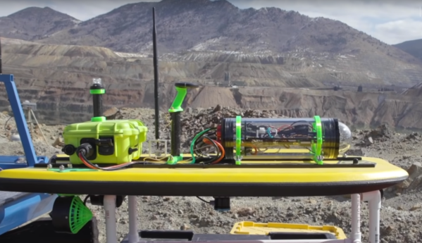
When they first started, the only tool they had available was a rifle. Scaring birds this way is not the most effective way for all species, though, so lately they have been turning to other tools. One of which is a custom boat built on a foam bodyboard which uses a plethora of 3D printed parts and sensors to allow the operator to remotely pilot the boat on the toxic lake. The team also has a drone to scare birds away, plus an array of other tools like high-powered lasers, propane cannons, and various scopes in order to put together the most effective response to help save wildlife.
While this strategy runs the gamut of the tools most commonly featured here, from 3D printers to drones to lasers, the only thing that’s missing is some automation like we have seen with other drone boat builds we’ve featured in the past. It takes quite a bit of time to continually scare birds off this lake, even through the winter, so every bit of help the team can get could go even further.