Small DC motors are easy to find — you can harvest dozens from old printers and copiers. You might even get a few with decent gearboxes too. But will you get exactly the motor with exactly the gearing your project needs? Unlikely, but you can always just print a gearbox to get exactly what you need.
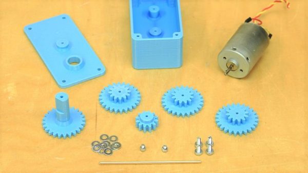
There’s nothing fancy about [fortzero]’s gearboxes. The motors are junk bin specials, and the gears are all simple spur gears 3D-printed from PLA. There are four gears in the train, each with a 2:1 reduction, giving a 16:1 overall ratio. The gears ride on brass shafts that are press-fit into the housing, and there’s not a bearing in sight — just a few washers to keep the gears spaced apart and plenty of grease. Despite the simplicity, the gearboxes turned out to be pretty capable, lifting a 3.5 kg load. The design files are available and should make it easy for you to get just the ratio you want for the motor you have.
Of course more complicated gearboxes are possible with a 3D printer, including a split-harmonic planetary gear, or a strain wave gear using a timing belt. No 3D printer? No problem! Just build a LEGO gearbox.
Continue reading “Customize Your Ratios With A 3D-Printed Gearbox”