Differential Drive Doesn’t Quite Work As Expected

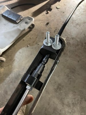
Placing two motors together in a shared drive is a simple enough task. By using something like a chain or a belt to couple them, or even placing them on the same shaft, the torque can be effectively doubled without too much hassle. But finding a way to keep the torque the same while adding the speeds of the motors, rather than the torques, is a little bit more complicated. [Levi Janssen] takes us through his prototype gearbox that attempts to do just that, although not everything works exactly as he predicts.

The prototype is based on the same principles as a differential, but reverses the direction of power flow. In something like a car, a single input from a driveshaft is sent to two output shafts that can vary in speed. In this differential drive, two input shafts at varying speeds drive a single output shaft that has a speed that is the sum of the two input speeds. Not only would this allow for higher output speeds than either of the two motors but in theory it could allow for arbitrarily fine speed control by spinning the two motors in opposite directions.

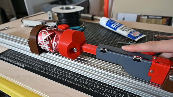
The first design uses two BLDC motors coupled to their own cycloidal drives. Each motor is placed in a housing which can rotate, and the housings are coupled to each other with a belt. This allows the secondary motor to spin the housing of the primary motor without impacting the actual speed that the primary motor is spinning. It’s all a lot to take in, but watching the video once (or twice) definitely helps to wrap one’s mind around it.

The tests of the drive didn’t go quite as planned when [Levi] got around to measuring the stall torque. It turns out that torque can’t be summed in the way he was expecting, although the drive is still able to increase the speed higher than either of the two motors. It still has some limited uses though as he notes in the video, but didn’t meet all of his expectations. It’s still an interesting build and great proof-of-concept otherwise though, and if you’re not clear on some of the design choices he made there are some other builds out there that take deep dives into cycloidal gearing or even a teardown of a standard automotive differential.

Continue reading “Differential Drive Doesn’t Quite Work As Expected”

Give 3D Printed Plastic A Well-Worn Metal Look

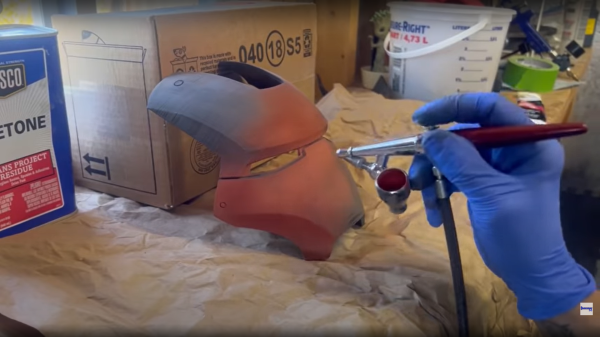
Affordable 3D printers let us turn ideas into physical reality without a big expensive workshop, but with their power came some disadvantages. The nature of FDM printers impart layer lines and nozzle ridges in the parts they produce. They can be minimized with optimized print settings, but never eliminated. [Emily Velasco] loves the power of 3D printing but not how the parts look. So she put in the effort to make 3D-printed plastic look like distressed metal and showed us how she did it. (Video also embedded after the break.)

This video is a follow-up to her Pet Eye project in response to feedback on Twitter. She had mentioned that the  salvaged metal box for Pet Eye wasn’t quite big enough to hold everything, so she had to extend its internal volume with a 3D print box on the back. It fit in so well that the offhand comment surprised many people who wanted to know more about how it was done. So she designed a demonstration cube covered with mechanical characteristics, and gave us this walkthrough of its transformation.

Continue reading “Give 3D Printed Plastic A Well-Worn Metal Look”

Full Size 3D-Printed Wind Turbine

Wind energy isn’t quite as common of an alternative energy source as solar, at least for small installations. It’s usually much easier just to throw a few panels and a battery together than it is to have a working turbine with many moving parts that need to be maintained when only a small amount of power is needed. However, if you find yourself where the wind blows but the sun don’t shine, there are a few new tools available to help create the most efficient wind turbine possible, provided you have a 3D printer.

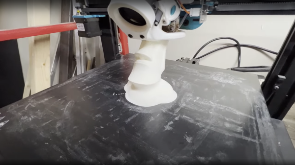
[Jan] created this turbine with the help of QBlade, a piece of software that helps design turbine blades. It doesn’t have any support for 3D printing though, such as separating the blades into segments, infill, and attachment points, so [Jan] built YBlade to help take care of all of this and made the software available on the project’s GitHub page. The blades are only part of this story, though. [Jan] goes on to build a complete full-scale wind turbine that can generate nearly a kilowatt of power at peak production, although it does not currently have a generator attached and all of the energy gets converted to heat.

While we hope that future versions include a generator and perhaps even pitched blades to control rotor speed, [Jan] plans to focus his efforts into improving the blade design via the 3D printer. He is using an SLA printer for these builds, but presumably any type of printer would be up to the task of building a turbine like this. If you need inspiration for building a generator, take a look at this build which attempted to adapt a ceiling fan motor into a wind turbine generator.


Trippy Tripteron Kinematics Brainteaser

[JK Lee] has been experimenting with a monorail tripteron motion control system (video, embedded below) and trying to improve performance with varying tweaks to the design and with varying degrees of success. But [JK] is enjoying this project — he was inspired by an idea that maker [Nicholas Seward] proposed — building a tripteron on two rails (video), or even building one on a single rail (video). He is making good progress, most recently working on solving a vertical bounce issue. He is focusing on the middle arm, as this arm carries most of the weight. You can see a brief video explanation of the kinematics of the monorail tripteron that [JK] made (he warns us that English is not his native language, so focus on the equations and diagrams and not the grammar).

If you’re not familiar with the tripteron, it was conceived, along with the quadrupteron, at the Robotics Laboratory at Université Laval in Canada and patented by their researchers back in 2004. We wrote about an early implementation of a tripteron by [Apsu] back in 2016. These recent experiments, reducing the mechanism down to a single or double rail, are interesting.

Other than cool projects for makers like [Nicholas] and [JK] who enjoy tinkering, are there any applications of tripterons and/or quatrupterons in the real world? Let us know in the comments below. Thanks to [Littlejohn] for sending in the tip.

Continue reading “Trippy Tripteron Kinematics Brainteaser”

3D Printed Flip Dots

Displays have come a long way in the last few decades, but none can deliver the mesmerizing visual and audio experience of a large flip dot display. Both old panels and new panels can be expensive and difficult to source, so [Larry Builds] made his own flip dots with the help of 3D printing.

Flip dots are driven by a pair of electromagnetic posts that attract or repel a magnet embedded in the dot, and [Larry Builds] version is no different. For the electromagnets, he used M3 threaded rod with enamel wire wound around them using a drill. At first, he used a large magnet in the center of the 3D printed dot, but the magnetic field was large and strong enough to flip the surrounding dots in an array. He then changed the design to a small 4 mm diameter magnet in the edge that aligns directly with the electromagnets. This design looks very similar to those used by Breakfast for their massive installations. By modifying electromagnets and adding spacers around the magnets, he was able to reduce the operating current from 2 A to below 500 mA. [Larry Builds] also breadboarded a basic driver circuit consisting of H-bridges multiplexed to rows and columns with diodes.

We will be keeping a close eye on this project, and we look forward to seeing it evolve further. It’s definitely on our “things to build” list. We’ve embedded multiple videos after the break showing the progress thus far.

We’ve covered several interesting flip dot projects, including a water level indicator that doesn’t use any electronics and another that is crocheted. Continue reading “3D Printed Flip Dots”

3D Printing A Centrifugal Water Pump

Once upon a time, 3D printing was about churning out tiny Yodas and Pikachus, but these days, useful things are regularly 3D printed too. A great example is this centrifugal water pump that can really deliver the juice, courtesy of  [Connor].

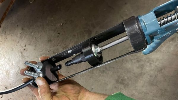
The pump’s housings and impeller are all 3D printed in PLA, as well as the inlet which is designed for a 2L soda bottle to screw into. Gaskets are printed in pliable TPU to help seal the housings. There are a few ball bearings inside to allow the impeller to spin nicely, too, with hex head fasteners used to hold everything together and a long bolt used as the main impeller shaft. Notably, no shaft seal is included, so the pump does leak a bit, but it’s not a major concern assuming you’re just pumping water and don’t mind spilling a bit of excess. Turned with a drill at 1800 rpm, the pump is able to achieve a flow rate of 13 litres per minute, or a maximum head of 1.2 meters. The design is on Onshape, for the curious.

It’s a great example of how 3D printing can allow the creation of machines with complex geometry without the need for advanced machining skills. Instead, all the hard work is done on the CAD side of things. We’ve seen 3D printed pumps put to real work before, too, like this fertilizer dispenser. Video after the break.

Continue reading “3D Printing A Centrifugal Water Pump”

Finite Element Analysis Vs Real World

In advanced engineering circles, the finite element method — or, more commonly, finite element analysis — is a real staple. With the advent of more powerful home computers, though, even your home projects can benefit. The technique itself is very general, but you usually see it used for structural analysis. However, you might wonder how well it corresponds to reality. That is if analysis shows a segment of your part is weak (or strong) does that hold true when you actually build the part? [Fiveohno] wondered the same thing and decided to do some testing, which you can see in the video below.

Of course, like any simulation, the accuracy will only be as good as your data input and model. But if you work carefully, it should match up pretty well to the real world, so it is interesting to see the results of a real-world test. In fact, a video from Solidworks that shows a similar part points out — inadvertently — what not to do. For example, the force used in that analysis was too low and at a point where the part was at relatively low stress instead of at the maximum stress.

Continue reading “Finite Element Analysis Vs Real World”