Flattening The Exhaust Of A Laser Cutter To Save Space

From laser cutters to 3D printers, having an exhaust duct at the back of a machine is a very common sight. However, these tend to be rather bulky, claiming many centimeters of precious space behind a machine even if you’d want to push it right up against a wall. This issue annoyed [TheNeedleStacker] over on YouTube so much that he had a poke at solving this problem with angled exhaust ducts, all hopefully without impairing its basic function.

Smoke machine and laser for some air ducting rave vibes. (Credit: TheNeedleStacker, YouTube)
Smoke machine and laser for some air ducting rave vibes.

Although there are some online offerings for angled exhaust port extenders, these do not quite fit the required 6″ diameter. Reducing the problem to just a matter of cross section area for simplicity’s sake, that means a 19″ wide duct at a depth of 1.5″. Making sure the transition from the tube to the flat duct doesn’t become an impediment is the tricky part, so the approach here was to mostly ignore it and just make a functional prototype to get an idea of how a direct approach worked.

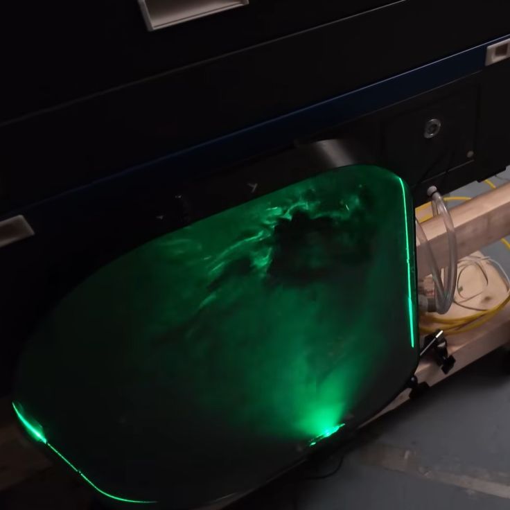
Installing the contraption worked out fine, and subsequent testing showed that although it seems to slightly reduce the effective airflow compared to the flex tubing, it is absolutely rad to look at with the transparent cover and some laser light to illuminate all that’s happening inside.

While some optimization work on the duct transitions can undoubtedly eke out more performance, it’s certainly not bad for a quick project.

Continue reading “Flattening The Exhaust Of A Laser Cutter To Save Space”

Ski Slopes For Laser Imaging

Lasers are cool and all, but they can be somewhat difficult to control at times. This is especially true when you have hundreds, thousands, or millions of lasers you need to steer. Fortunately, the MITRE Corporation might have created exactly what’s needed to accomplish this feat. While you might expect this to be done in a similar fashion as a DLP micro mirror array, these researchers have created something a bit different.

A ski slope like a MEMS array is used to contort light as needed. Each slope is able to be controlled in such a way so precise that entire images are able to be displayed by the arrays. This is done by using a “piezo-opto-mechanical photonic integrated circuit” or (POMPIC). Each slope is constructed from SiO2, Al, AlN, and Si3N4. All of these are deposited in such a way to allow the specific bending needed for control.

While quantum computing hasn’t hit these slopes yet, that doesn’t mean you can’t look into the other puzzles needed for the quantum revolution. Quantum computing is something that people have been trying for a long time to get right. Big claims come from all the big players. Take Microsoft, for example, with claims of using Majorana zero mode anyons for topological quantum computing.

Continue reading “Ski Slopes For Laser Imaging”

Drawing Tablet Controls Laser In Real-Time

Some projects need no complicated use case to justify their development, and so it was with [Janne]’s BeamInk, which mashes a Wacom pen tablet with an xTool F1 laser engraver with the help of a little digital glue. For what purpose? So one can use a digital pen to draw with a laser in real time, of course!

Pen events from the drawing tablet get translated into a stream of G-code that controls laser state and power.

Here’s how it works: a Python script grabs events from a USB drawing tablet via evdev (the Linux kernel’s event device, which allows user programs to read raw device events), scales the tablet size to the laser’s working area, and turns pen events into a stream of laser power and movement G-code. The result? Draw on tablet, receive laser engraving.

It’s a playful project, but it also exists as a highly modular concept that can be adapted to different uses. If you’re looking at this and sensing a visit from the Good Ideas Fairy, check out the GitHub repository for more technical details plus tips for adapting it to other hardware.

We’re reminded of past projects like a laser cutter with Etch-a-Sketch controls as well as an attempt to turn pen marks into laser cuts, but something about using a drawing tablet for real-time laser control makes this stand on its own.

Using A Fiber Laser To Etch 0.1 Mm PCB Traces

Creating PCBs at home is quite easy these days (vias not withstanding), but even the best DIY methods usually can’t match the resolution offered by commercial PCB production lines. Large traces are easy enough to carve out of copper-backed FR1 or FR4 with even a mill, what if you need something more like 100 µm sized traces with similar clearance? This is what [Giangix] has been experimenting with, using both a fiber laser and chemical etching to see what approach gives the best results.

The thin copper clad boards are put on the 20 Watt fiber laser and held in place with the vacuum table that [Giangix] previously made, using the power of suction to make sure the board doesn’t move. The used laser specifies a minimum line width of 0.01 mm, so that’s clearly fine enough to engrave away the chemical resist layer that is sprayed on top of the copper layer.

After some experimentation, it was found that increasing the trace clearance between the 0.1 mm traces to a hair above 0.1 mm was necessary for the subsequent chemical etching step to work the best, as otherwise some copper was still likely to remain. The chemical etching bath mixture consists of hydrochloric acid and hydrogen peroxide, in a ratio of 2 mL water to 2 mL 30% HCl and 2 drops of 35% H2O2. This is agitated for 90 s to get a pretty good result.

Although the final resistance measurements on the traces is a bit higher than theoretical, comments suggest that maybe some of the copper got removed along with the removal of the resist layer. Perhaps the most interesting question here is whether directly ablating the copper using the fiber laser would give even better results and bypass the etching chemicals.

Continue reading “Using A Fiber Laser To Etch 0.1 Mm PCB Traces”

A man's hand is shown holding a 3D-printed structure. The structure is hollow and has a fiber-optic cable leading to it. Blue light shines from a hole in the structure. In the background, a laser module is coupled to a fiber-optic cable.

Building A Laser-Driven Photoacoustic Speaker

An MRI scan is never a pleasant occasion – even if you aren’t worried about the outcome, lying still in a confined, noisy space for long periods of time is at best an irksome experience. For hearing protection and to ameliorate boredom or claustrophobia, the patient wears headphones. Since magnets and wires can’t be used inside an MRI machine, the headphones have to literally pipe the sound in through tubes, which gives them poor sound quality and reduces the amount of noise they can block. [SomethingAboutScience], however, thinks that photoacoustic speakers could improve on these, and built some to demonstrate.

Continue reading “Building A Laser-Driven Photoacoustic Speaker”

Fiber Optic Lamp Modified To Be Scarily Bright

[Brainiac75] is a fan of fiber optic lamps, except for one thing—they’re often remarkably dim. Thus, they set out to hack the technology to deliver terrifying amounts of light while still retaining their quirky charm.

Older fiber optic lamps use a dim filament lamp or halogen lamp to light them up. They also often feature a spinning color disk to vary the light patterns, which does have the side effect of absorbing some of the already-limited light output.

When it came to upgrading his own decades-old lamp, [Braniac75] decided to initially stick within the specs of the original halogen lamp. The fixture was rated for 12 volts at 5 watts, with a GU4/GZ4 compatible base, and white light was desired so the color wheel could still do its thing.  Swapping out the original 5 W halogen for a 2.5 W LED unit brought a big upgrade in brightness, since the latter is roughly equivalent to a 20 W halogen in light output. Upgrading to a 4.2 W LED pushed things even further, greatly improving the look of the lamp.

The video also explores modding a modern fiber optic lamp, too. It was incredibly cheap, running off batteries and using a single color-changing LED to illuminate the fibers. [Braniac75] decided to try illuminating the plastic fibers with an RGB stage lighting laser rig—namely, the LaserCube Ultra 7.5 W from Wicked Lasers. With this kind of juice, the fiber lamp is eye-searingly bright, quite literally, and difficult to film. However, with the laser output dialed way down, the lamp looks amazing—with rich saturated colors dancing across the fiber bundle as the lasers do their thing.

If you’ve ever wanted to build a fiber lamp that doesn’t look like a cheap gimmick, now you know how. We’ve looked at weird applications for these lamps before, too.

Continue reading “Fiber Optic Lamp Modified To Be Scarily Bright”

The Random Laser

When we first heard the term “random laser,” we did a double-take. After all, most ordinary sources of light are random. One defining characteristic of a traditional laser is that it emits coherent light. By coherent, in this context, that usually includes temporal coherence and spatial coherence. It is anything but random. It turns out, though, that random laser is a bit of a misnomer. The random part of the name refers to how the device generates the laser emission. It is true that random lasers may produce output that is not coherent over long time scales or between different emission points, but individually, the outputs are coherent. In other words, locally coherent, but not always globally so.

That is to say that a random laser might emit light from four different areas for a few brief moments. A particular emission will be coherent. But not all the areas may be coherent with respect to each other. The same thing happens over time. The output now may not be coherent with the output in a few seconds.

Baseline

A conventional laser works by forming a mirrored cavity, including a mirror that is only partially reflective. Pumping energy into the gain medium — the gas, semiconductor, or whatever — produces more photons that further stimulate emission. Only cavity modes that satisfy the design resonance conditions and experience gain persist, allowing them to escape through the partially reflecting mirror.

The laser generates many photons, but the cavity and gain medium favor only a narrow set of modes. This results in a beam that is of a very narrow band of frequencies, and the photons are highly collimated. Sure, they can spread over a long distance, but they don’t spread out in all directions like an ordinary light source. Continue reading “The Random Laser”