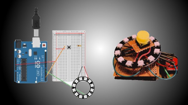
The scientific community cannot always agree on how much water a person needs in a day, and since we are not Fremen, we should give it more thought than we do. For many people, remembering to take a sip now and then is all we need and the H2gO is built to remind [Angeliki Beyko] when to reach for the water bottle. A kitchen timer would probably get the job done, but we can assure you, that is not how we do things around here.
A cast silicone droplet lights up to show how much water you have drunk and pressing the center of the device means you have taken a drink. Under the hood, you find a twelve-node NeoPixel ring, a twelve millimeter momentary switch, and an Arduino Pro Mini holding it all together. A GitHub repo is linked in the article where you can find Arduino code, the droplet model, and links to all the parts. I do not think we will need a device to remind us when to use the bathroom after all this water.
We’re all familiar with the wide variety of Arduino development boards available these days, and we see project after project wired up on a Nano or an Uno. Not that there’s anything wrong with that, of course, but there comes a point where some hobbyists want to move beyond plugging wires into header sockets and build the microcontroller right into their project. That’s when one generally learns that development boards do a lot more than break the microcontroller lines out to headers, and that rolling your own design means including all that supporting circuitry.
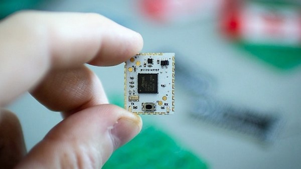
To make that transition easier, [Sean Hodgins] has come up with a simple Arduino-compatible module that can be soldered right to a PCB. Dubbed the “HCC Mod” for the plated half-circle castellations that allows for easy soldering, the module is based on the Atmel SAMD21 microcontroller. With 16 GPIO lines, six ADCs, an onboard 3.3 V regulator, and a reset button, the module has everything needed to get started — just design a PCB with the right pad layout, solder it on, and surround it with your circuitry. Programming is done in the familiar Arduino IDE so you can get up and running quickly. [Sean] has a Kickstarter going for the modules, but he’s also releasing it as open source so you’re free to solder up your own like he does in the video below.
It’s certainly not the first dev module that can be directly soldered to a PCB, but we like the design and can see how it would simplify designs. [Sean] as shown us a lot of builds before, like this army of neural net robots, so he’ll no doubt put these modules to good use.
Lip syncing for computer animated characters has long been simplified. You draw a set of lip shapes for vowels and other sounds your character makes and let the computer interpolate how to go from one shape to the next. But with physical, real world puppets, all those movements have to be done manually, frame-by-frame. Or do they?
He toyed around with a number of approaches for making the lip mechanism before coming up with one that worked the way he wanted. The lips are shaped using guitar wire soldered to other wires going to servos further back in the head. Altogether there are four servos for the lips and one more for the jaw. There isn’t much sideways movement but it does enough and lets the brain fill in the rest.
On the software side, he borrows heavily from the tools used for lip syncing computer-drawn characters. He created virtual versions of the five servo motors in Adobe Animate and manipulates them to define the different lip shapes. Animate then does the interpolation between the different shapes, producing the servo positions needed for each frame. He uses an AS3 script to send those positions off to an Arduino. An Arduino sketch then uses the Firmata library to receive the positions and move the servos. The result is entirely convincing as you can see in the trailer below. We’ve also included a video which summarizes the iterations he went through to get to the finished Billy Whiskers or just check out his detailed website.
[Jame’s] work shows that there many ways to do stop motion animation, perhaps a part of what makes it so much fun. One of those ways is to 3D print a separate object for each character shape. Another is to make paper cutouts and move them around, which is what [Terry Gilliam] did for the Monty Python movies. And then there’s what many of us did when we first got our hands on a camera, move random objects around on our parent’s kitchen table and shoot them one frame at a time.
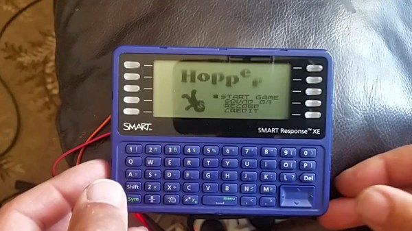
Cheap second-hand hardware is usually a fertile ground for hacking, and by looks of this project, the digital classroom aids that were all the rage a few years back are no exception. [is0-mick] writes in to tell us how he managed to hack one of these devices, a SMART Reponse XE, into an Arduboy compatible game system. As it turns out, this particular gadget is powered by an ATmega128RFA, which is essentially an Arduino-compatible AVR microcontroller with a 2.4GHz RF transceiver tacked on. This makes it an extremely interesting platform for hacking, especially since they are going for as little as $3 USD on eBay.
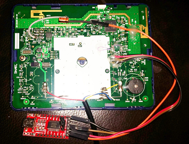
There’s no USB-Serial converter built into the SMART Response XE, so you’ll need to provide your own external programmer to flash the device. But luckily there’s a labeled ISP connector right on the board which makes it pretty straightforward to get everything wired up.
Of course, getting the hardware working was slightly more complicated than just flashing an Arduino Sketch onto the thing. [is0-mick] has provided his bootloader and modified libraries to get the device’s QWERTY keyboard and ST7586S controlled 384×160 LCD working.
Playing games is fun, but when his friend [en4rab] sent him the SMART Response XE to fiddle with, the goal was actually to turn them into cheap 2.4 GHz analyzers similar to what was done with the IM-ME. It seems they’re well on their way, and [is0-mick] invites anyone who might be interested in filling in some of the blanks on the RF side to get involved.
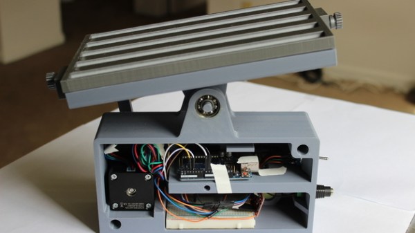
Lab equipment is often expensive, but budgets can be tight and not always up to getting small labs or researchers what they need. That’s why [akshay_d21] designed an Open Source Lab Rocker with a modular tray that uses commonly available hardware and 3D printed parts. The device generates precisely controlled, smooth motion to perform automated mild to moderately aggressive mixing of samples by tilting the attached tray in a see-saw motion. It can accommodate either a beaker or test tubes, but since the tray is modular, different trays can be designed to fit specific needs.
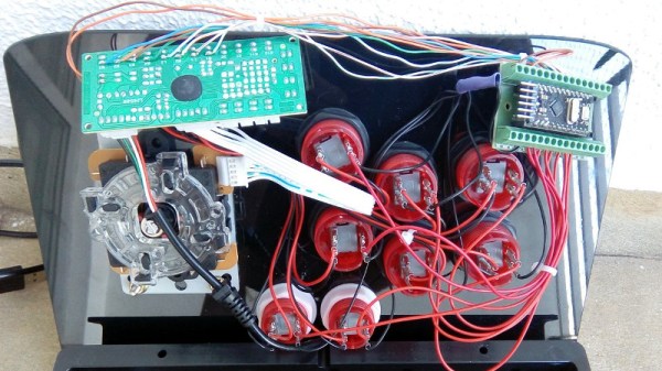
As if you already weren’t agonizing over whether or not you should build your own arcade cabinet, add this one to the list of compelling reasons why you should dedicate an unreasonable amount of physical space to playing games you’ve probably already got emulated on your phone. [Rodrigo] writes in to show off his project to add some flair to the lighted buttons on his arcade controller. (Google Translate)
The wiring for this project is about as easy as you’d expect: the buttons connect to the digital inputs on the Arduino, and the LEDs on the digital outputs. When the Arduino code sees the button getting pressed, it brings the corresponding LED pin high and starts a fade out timer using the SoftPWM library by [Brett Hagman].
It’s worth noting that the actual USB interface is being done with a stand-alone controller, so the Arduino here is being used purely to drive the lighting effects. The more critical reader might argue that you could do both with a single microcontroller, but [Rodrigo] was in a classic “Use what you’ve got” situation, and already had a USB controller on hand.
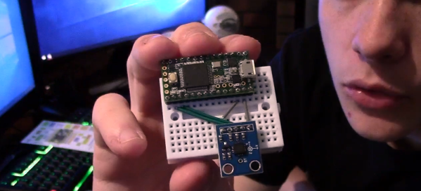
[Carson] didn’t know how to use an accelerometer until he wired one up to a Teensy and put it all in a hat. The result is a joystick that will probably cause you neck problems if you play video games for very long. You can see a video of how the device came to be and how it works, below.
We liked the approach of building up the circuit and testing it before integrating it with the hat. He used a small breadboard with half the Teensy pins hanging off. That seems to work, although we’d be worried about something shorting or floating pins causing issues. Of course, if you drove the disconnected pins as outputs or inputs with pullups that might not be a big deal.