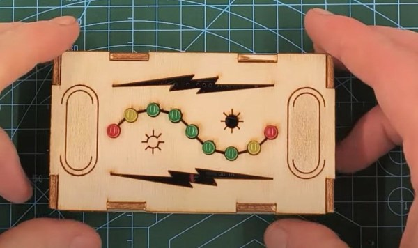
Maybe it’s just us, but isn’t it kind of amazing that in a world of pretty darn realistic games, PONG is still thrilling to play? This 1D implementation by [newsonator] is about as exciting as it gets.
 It works like you’d probably expect — the light moves back and forth between the two players. Keep it in the green and you have a nice, gentle volley going. Let it hit your red LED and you’ve lost a point. But if you can push your button while your yellow LED is lit, the light speeds up tremendously until the next button press in the green.
Our only wish is that subsequent yellow-light button presses would make it speed up even more. But there are really just the two speeds with the current programming.
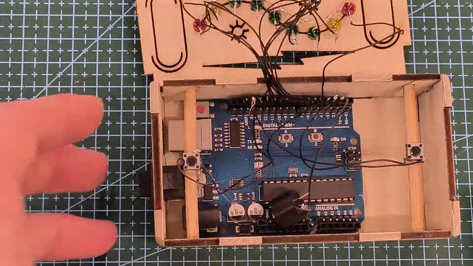
Inside the cool laser-cut box is an Arduino Uno and a 9V battery, plus a current-limiting resistor and the all-important buzzer. We like how [newsonator] wired up the LEDs to the Arduino by soldering them to a row of header pins and sticking that into the Arduino so it can be used in other projects down the line. We also like how [newsonator] shoved a couple of dowels through the box to ultimately support the two buttons.
Check out the intro video after the break for the overall details. The build is done over a few different short videos which follow.
Although this is pretty small, it isn’t quite the minimum viable.