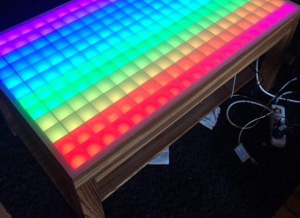
It’s an ambitious build for sure — you don’t start with $500 worth of wood if you don’t intend for the finished product to dazzle. And this 240-pixel touch-sensitive light box coffee table does indeed dazzle.
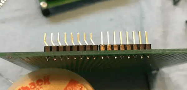
Sometimes when we see such builds as these, fit and finish take a back seat to function. [dasdingo89] bucks that trend with a nicely detailed build, starting with the choice of zebrawood for the table frame. The bold grain and the frosted glass top make for a handsome table, but what lurks beneath the glass is pretty special too. The 240 WS2812 modules live on custom PCBs, each thoughtfully provided with connectors for easy service. There’s also an IR transmitter-receiver pair on each board to detect when something is placed over the pixel. The pixel boards are connected to custom-built shift register boards for the touch sensors, and an Arduino with Bluetooth runs the whole thing. Right now the table just flashes and responds to hand gestures, but you can easily see this forming the basis of a beautiful Tetris or Pong table.
This build reminds us a little of this pressure-sensitive light floor we featured recently, which also has some gaming possibilities. Maybe [dasdingo89] and [creed_bratton_] should compare notes and see who can come up with the best games for their platform.
[via r/DIY and a tip from emptycanister]
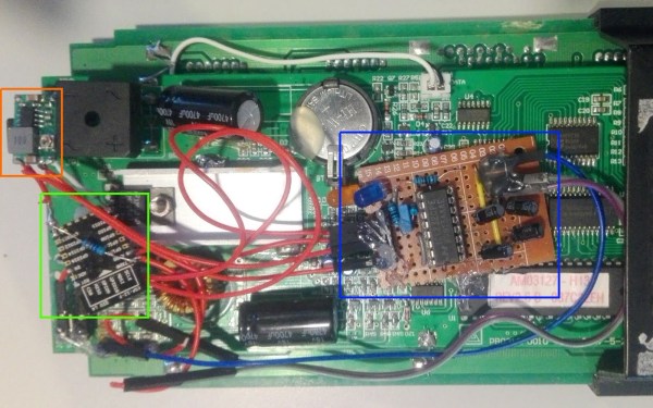

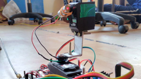
 sensor input, and the servo. A button press tells the Arduino to start the race by pulling the start gate down and starting the timer. When the light sensor is covered, the timer for that lane stops. The time is shown for each lane using a different colored 4-digit 7-segment LED.