Play Music With Your Painting Using Teensy

[sab-art], a collaboration between [Sophia Brueckner] and [Eric Rosenbaum], has created a touch-sensitive musical painting. Initially, basic acrylic paint is used for the majority of the canvas. Once that is dry, conductive paint is used to make the shapes that will be used for the capacitive touch sensing. As an added step to increase the robustness, nails are hammered through each painted shape and connected with wiring in the back of the painting. These wires are then connected to the inputs of a Teensy++ 2.0, using Arduino code based on MaKey MaKey to output MIDI. The MIDI is then sent to a Mac Mini which then synthesizes the sound using Ableton Live.  Any MIDI-processing software would work, though. For this particular painting, external speakers are used, but incorporating speakers into your own composition is certainly possible.

A nice aspect of this project is that it can be as simple or as complex as you choose. Multiple conductive shapes can be connected through the back to the same Teensy input so that they play the same sound. While [sab-art] went with a more abstract look, this can be used with any style. Imagine taking a painting of Dogs Playing Poker and having each dog bark in its respective breed’s manner when you touch it, or having spaceships make “pew pew” noises. For a truly meta moment, an interactive MIDI painting of a MIDI keyboard would be sublime. [sab-art] is refining the process with each new painting, so even more imaginative musical works of art are on the horizon. We can’t wait to see and hear them!

Continue reading “Play Music With Your Painting Using Teensy”

Hardware for a ST4 to USB interface

Cheap USB Control For Your Telescope

There’s many complex systems for automatically pointing a telescope at an object in the sky, but most of them are too expensive for the amateur astronomer. [Kevin]’s Arduino ST4 interface lets you connect your PC to a reasonably priced motorized telescope mount, without ripping it apart.

The ST4 port is a very basic interface. There’s one pin per direction that the mount can move, and a common pin. This port can be added to just about any motorized mount with some modification to the controller. To connect to an Arduino, a TLP521-4 quad optoisolator is used. This keeps the Arduino and PC fully isolated from the motor circuits. but lets the Arduino take control of the mount.

With the hardware in place, [Kevin] cranked out some software which is available on Google Code. A simple Arduino sketch provides the USB interface, and a custom driver allows the ASCOM Platform to control the mount. Since many astronomy software tools support ASCOM, this allows the mount to be controlled by existing software.

With the interface in place, the mount can be used to find objects (GOTO) and automatically follow them with high accuracy (autoguiding). You can watch the telescope move on its own after the break.

Continue reading “Cheap USB Control For Your Telescope”

Blackboard Digitization For Under $40

Digital White/Black Boards or “Smart Boards” are very useful in modern classrooms, but their high cost often makes it difficult to convince administrators from loosening their purse strings. Cooper Union’s 2nd annual HackCooper event in New York wanted students to design and build hardware and software projects that both solve real problems and spark the imagination. At the 24 hour hackathon, the team of [harrison], [david] and [caleb] decided to put together a low-cost and simple solution to digitizing classroom black board content.

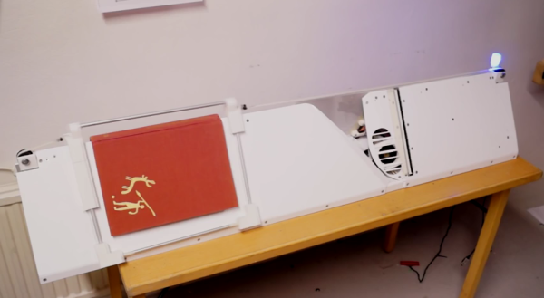
A chalk-holder is attached to two strings, each connected over a pulley to a weight. The weights slide inside PVC pipes at the two sides of the black board. Ultrasonic sensors at the bottom of each tube measure the distance to the weights. The weights sit in static equilibrium, so they serve the purpose of keeping the string taut without negatively interfering with the writer.

With a couple of calibration points to measure the extent of displacement of each weight, board width can be determined, making it easy to adapt to different sizes of boards. Once calibrated, the system can determine position of the chalk over the board based on some trigonometrical calculations. Since they had just 24 hours to hack the system together, they had to use a hand operated radio with a couple of buttons to provide user control. Pressing the “Write” button starts transmitting chalk movements to the digital screen. A second button on the radio remote serves to “Erase” the digital screen. After receiving the chalk position data, they had to do a fair amount of processing to eliminate noise and smooth out the writing on the digital screen.

A server allows the whole class to receive the chalk board data in real time. After each “Erase” command, the chalk board state is saved and logged on the server, thus allowing previous content to be viewed or downloaded. If only text is written, optical character recognition can be used to further digitize the content.

What makes the project really useful is the low cost. The sensors cost a dollar. The other parts – PVC pipe, weights/pulleys, Arduino and the Radio key fob – were all bought for under 40 dollars. For some additional cost (and maybe more time in their case) they could have automated the detection of when the chalk was actually doing the writing. The team have made their code available on Github. For a Chalk board at the other end of the cost spectrum, check this one out. Video below.

Continue reading “Blackboard Digitization For Under $40”

Non-Arduino Powered By A Piece Of Computing History

Sometimes it is a blessing to have some spare time on your hands, specially if you are a hacker with lots of ideas and skill to bring them to life. [Matt] was lucky enough to have all of that and recently completed an ambitious project 8 months in the making – a Non-Arduino powered by the giant of computing history – Intel’s 8086 processor. Luckily, [Matt] provides a link to describe what Non-Arduino actually means; it’s a board that is shield-compatible, but not Arduino IDE compatible.

He was driven by a desire to build a single board computer in the old style, specifically, one with a traditional local bus. In the early days, a System Development Kit for Intel’s emerging range of  microprocessors would have involved a fair bit of discrete hardware, and software tools which were not all too easy to use.

Back in his den, [Matt] was grappling with his own set of challenges. The 8086 is a microprocessor, not a microcontroller like the AVR, so the software side of things are quite different. He quickly found himself locking horns with complex concepts such as assembly bootstrapping routines, linker scripts, code relocation, memory maps, vectors and so on. The hardware side of things was also difficult. But his goal was learning so he did not take any short cuts along the way.

[Matt] documented his project in detail, listing out the various microprocessors that run on his 8OD board, describing the software that makes it all run, linking to the schematics and source code. There’s also an interesting section on running Soviet era (USSR) microprocessor clones on the 8OD. He is still contemplating if it is worthwhile building this board in quantities, considering it uses some not so easy to source parts. If you are interested in contributing to the project, you could get lucky. [Matt] has a few spares of the prototypes which he is willing to loan out to anyone who can can convince him that they could add some value to the project.

Continue reading “Non-Arduino Powered By A Piece Of Computing History”

remote circuit board

Ultimate Remote Is Ultimate

[Joedefa] had a Griffin Beacon Universal Remote that was collecting dust, and decided that it needed to stop collecting dust. He had a growing number of wireless devices in his house and found himself in need of a remote to control them all. The Griffin Beacon fit the bill, but most of his lights and outlets were RF controlled. So he did what hackers do best… broke out the screw driver and soldering iron and rewired it!

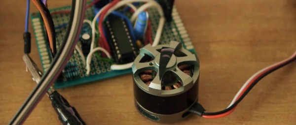
[Joedefa] is using an Attiny85 as the brains between an infrared LED and a RF transmit module (if anyone can identify the source of this module, please let everyone know in the comments).  A pair of red and green LEDs lets him know if the remote has received commands successfully.

It’s always nice to see a discontinued product made useful once more with a little ingenuity and an Arduino some hacking skill. Hat’s off to [Joedefa] for a righteous hack!

The Annoying Machine

The Useless Machine – a machine with a toggle switch, a mechanical arm, and something that only exists to turn itself off – is a staple of Instructables and builds from random workbenches the world over. It’s cliché, and now hackaday.io has a better project: The Annoying Machine, a machine that exists purely to annoy.

According to [unigamer], the Annoying Machine is the evil cousin of the Useless Machine. On the outside, it’s extremely simple: a switch labeled ‘on’ and ‘off’, and a hole for an LED. Turn the switch on, and the Annoying Machine will emit an annoying buzzing sound. Switch the Machine off, and the buzzing will go away. Then the switch will flick itself back to on. Insidious.

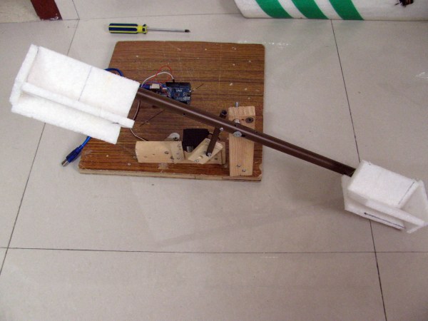
A switch and buzzer is easy enough, but the key component of this build is an actuated rocker switch. It’s basically a normal toggle switch with two additional terminals for a coil that can move the switch back and forth electronically. Throw in an Arduino, buzzer, battery, and a boost converter for the switch, and that’s just about all there is to it.

How to deactivate the Annoying Machine? There’s an accelerometer attached to the Arduino, and by throwing the box up in the air after flicking the switch off, it will reset. There are already plans for a Version 2 of the Annoying Machine that will be even louder and made out of aluminum. Anything to protect it from the inevitable hammers of frustration.

Video below.

Continue reading “The Annoying Machine”

Bill’s Arduino

Pokemon is a great game by itself, but when you realize that not all of the ‘mon are available in one game, trading is required for completion, and some pokemon aren’t available without either hacking or going to a Toys ‘R Us in 1997, you start to see how insidious this game can be. Figuring he could finally complete the game with an Arduino, [Pepijn] decided to build a pokemon storage system.

This build was inspired by an earlier post that also spoofed trades. Instead of building this project around a high-power micro, [Pepijn] decided to use an Arduino. The protocol Game Boys use to communicate with each other is extremely well documented, although that’s only half the battle. Each game using the link cable used specialized data structures for transfer, and after grepping through a disassembled Pokemon ROM,  [Pepijn] figured out how everything worked.

The completed hardware keeps one Pokemon in the EEPROM of an Arduino. It’s not very fast if you want to catch all 151 Pokemon in the Gen 1 games, but any way you look at it, you’re going to be catching a lot of Magikarp anyway.