rf detector circuit

Using An LED As A Simple RF Detector

When [b.kainka] set out to make the world’s simplest RF detector, he probably didn’t realize it would be as easy as it was. Consisting of only a handful of components and thirty eight lines of code, he was able to make an RF detector that works reasonably well.

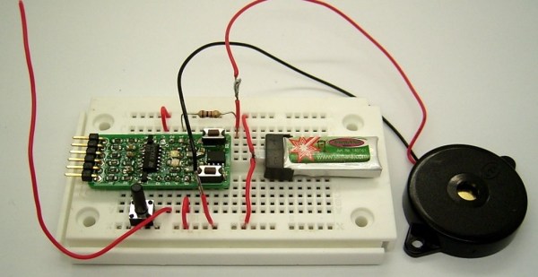
The microcontroller running the code is an ATtiny13 on a Sparrow board. He’s using an everyday LED as a detector diode and an internal pull-up resistor in the ATtiny13 for the bias voltage. The antenna runs off the LED’s anode. To make it sensitive enough, he switches on the pull-up resistor for a tiny fraction of time. Because an LED can act like a small capacitor, this charges it to a few volts. He then switches the pullup off, and the voltage across the LED will start to discharge. If there is an RF signal present, the discharge voltage will be less than the discharge voltage with no signal present.  Neat stuff.

Be sure to check out his Hackaday.io page linked at the top for full source, schematics and some videos demonstrating his project.

Continue reading “Using An LED As A Simple RF Detector”

An Introduction To Clock Dividers And Psychological Warfare

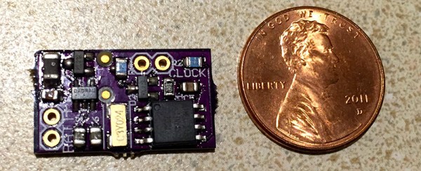
A while ago, [nsayer] was inspired by a Hackaday post to build one of the most insidious means of psychological warfare. I speak, of course, of the [Lord Vetinari] clock, a clock that ticks at random intervals, but still keeps accurate time. His build, the Crazy Clock, is a small controller board for off-the-shelf clock movements that adds the [Vetinari] feature to any clock by soldering only a few wires.

The Crazy Clock is a pretty simple device consisting of only a 32.768 kHz crystal, a microcontroller, and a few transistors to pulse the movement of a clock mechanism. While psyops is great, it recently occurred to [nsayer] that this device could be used for other build.

Since the output of the Crazy Clock doesn’t necessarily have to be connected to a clock movement, [nsayer] decided to connect a LED, generating a 60Hz flashing light for a phonograph strobe. This is easy with timer prescalers and clock dividers; the original 32.768 kHz signal is divided by 8 to produce a clock that ticks every 4.096 kHz.  Divide that again by 120, and you get 34 2/15. Yes, this is all stuff you learned in fourth grade, and if you’re smarter than a third grader you can eventually whittle a 32.768 kHz clock down to a nice, round, binary number – exactly what you need for computing time.

[nsayer] posted a 240 fps (vertical) video of his Crazy Clock blinking at 60 Hz. You can see that below.

Continue reading “An Introduction To Clock Dividers And Psychological Warfare”

In Which Robots Fight The Console Wars

Though the names have changed over the years, the console wars wage on. [moop] must have been feeling nostalgic for the NES vs. SEGA days when he started his current project, Foobot, which is a tabletop football (soccer) game played by robots that are controlled with classic NES and SEGA controllers.

Each team has two robots that tool around on laser-cut perspex wheels attached directly to 16,000RPM motors. An SN754410 controls the motors, and each robot has an ATtiny2313 brain. They all communicate with a single transmitter over their 433MHz 1402 radio receiver modules. To avoid collisions, [moop] used a packet system, wherein each robot has an ID. The messages all contain a robot ID, message payload, and checksum. The robots ignore messages addressed to others, and any message with an invalid checksum.

[moop] has made everything available on his github, including the PCB layouts and CAD files for the robot chassis and transmitter case. Watch them battle it out after the break. If the Foobots have riled you up about vintage gaming, check out these sweet arcade hacks.

Continue reading “In Which Robots Fight The Console Wars”

Auto-sleep Hacked In PC Speakers

We can commiserate with [HardwareCoder] who would rather not leave his PC speakers on all the time. The Creative T20 set that he uses turn off when you turn the volume knob all the way down until it clicks. So shutting them off means repositioning the volume each time they’re switched on again. This hack kills two birds with one stone by turning on and off automatically without touching that knob.

The system is based around an ATtiny45 and a few other simple components. It uses two ADCs to monitor the rear input channels of the PC speakers. If no sound is detected for more than one minute, the shutdown pin of the speakers’ amp chip is triggered. That’s not quite where the hack ends. We mentioned it monitors the rear input of the speakers, but it doesn’t monitor the front AUX input. An additional push button is used to disable the auto-sleep when using this front input. There is also a fancy PWM-based heartbeat on an LED when the speakers are sleeping.

[HardwareCoder] was worried that we wouldn’t be interested in this since it’s quite similar to a hack we ran a few years ago. We hope you’ll agree it’s worth another look. He also warned us that the demo video was boring. We watched it all anyway and can confirm that there’s not much action there but we embedded it below anyway.

Continue reading “Auto-sleep Hacked In PC Speakers”

image of control curcuit

Brighten Your Day With Motion Controlled Cabinet Light

[Thomas Snow] found himself in a bit of a pickle. His kitchen lights didn’t adequately light his counter-tops. So instead of inventing a light bending device that could warp space-time enough to get the light where it needs to go, he decided to take the easy road and installed a motion controlled LED strip under the cabinets.

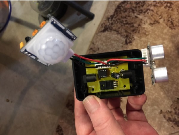
Now, these aren’t just any ‘ol motion control lights. Not only is [Thomas] able to turn the lights on and off with a wave of his hand, he can control the brightness as well. He’s doing the magic with an ultrasonic range sensor and PIR sensor. An ATTiny85 ties everything together to form the completed system.

The PIR sensor was incorporated because [Thomas] didn’t want to bug his pets with the 40kHz chirp from the ultrasonic sensor. So it only comes on when the PIR sensor sees your hand. Be sure to check out [Thomas’s] project for full source and schematics.

Continue reading “Brighten Your Day With Motion Controlled Cabinet Light”

ATtiny85 Does Over The Air NTSC

[CNLohr] has made a habit of using ATtiny microcontrollers for everything, and one of his most popular projects is using an ATTiny85 to generate NTSC video. With a $2 microcontroller and eight pins, [CNLohr] can put text and simple graphics on any TV. He’s back at it again, only this time the microcontroller isn’t plugged into the TV.

The ATtiny in this project is overclocked to 30MHz or so using the on-chip PLL. That, plus a few wires of sufficient length means this chip can generate and broadcast NTSC video.

[CNLohr] mentions that it should be possible to use this board to transmit closed captioning directly to a TV. If you’re looking for the simplest way to display text on a monitor with an AVR, there ‘ya go: a microcontroller and two wires. He’s unable to actually test this, as he lost the remote for his tiny TV from the turn of the millennium. Because there’s no way for [CNLohr] to enable closed captioning on his TV, he can’t build the obvious application for this circuit – a closed caption Twitter bot. That doesn’t mean you can’t.

Video below.

Continue reading “ATtiny85 Does Over The Air NTSC”

Controlling Analog with SPI

We Assume Control: SPI And A Digital Potentiometer

In the last video I demonstrated a Universal Active Filter that I could adjust with a dual-gang potentiometer, here I replace the potentiometer with a processor controlled solid-state potentiometer. For those that are too young to remember, we used to say “solid-state” to differentiate between that and something that used vacuum tubes… mostly we meant you could drop it without it breakage.

The most common way to control the everyday peripheral chips available is through use of one of the common Serial Protocols such as I2C and SPI.  In the before-time back when we had only 8 bits and were lucky if 7 of them worked, we used to have to memory map a peripheral or Input/Output (I/O) controller which means we had to take many control and data lines from the microprocessor such as Data, Address, Read/Write, system clocks and several other signals just to write to a couple of control registers buried in a chip.

Nowadays there is a proliferation of microcontrollers that tend to have built-in serial interface capability it is pretty straightforward to control a full range of peripheral functions; digital and analog alike.  Rather than map each peripheral using said data and address lines,which is a very parallel approach,  the controller communicates with peripherals serially using but a handful of signal lines such as serial data and clock. A major task of old system design, mapping of I/O and peripherals, is no longer needed.

Continue reading “We Assume Control: SPI And A Digital Potentiometer”