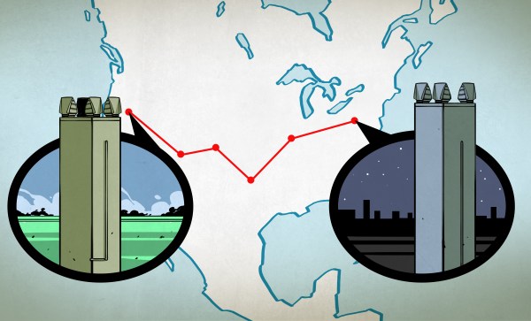
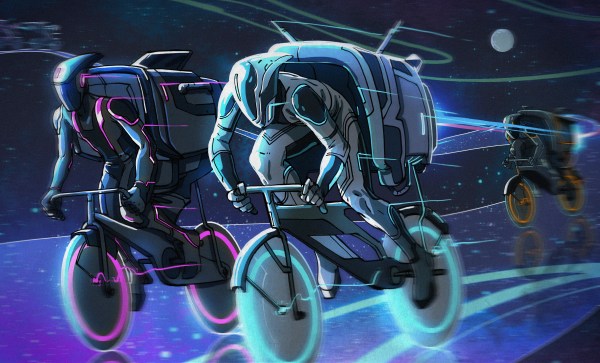
Retrotechtacular: ERNIE

Wherever you may live in the world, who do you wish to smile upon you and deliver good fortune? You may be surprised to discover that for a significant number of Brits this role is taken by someone called [Ernie].

What, [Jim Henson]’s Ernie from Sesame Street‘s famous duo Bert and Ernie? Sadly not, because the owner of a [Rubber Duckie] can’t offer you the chance of a million quid every month. Instead, [Ernie] is a computer that has been anthropomorphised in the national imagination. More properly referred to as E.R.N.I.E, for Electronic Random Number Indicator Equipment, he is the machine that picks the winning bond numbers for the Premium Bonds, a lottery investment scheme  run by the British Government.

Brits have been able to buy £1 bonds, up to 50,000 of them today, since the 1950s, and every month they are entered into a drawing from which ERNIE picks the winners. The top two prizes are a million pounds, but for most bond holders the best they can hope for is the occasional £25 cheque. Premium Bonds are often bought for young children so a lot of Brits will have a few, often completely forgotten. Prizes never expire, so if you are the holder of old bonds you should consider asking National Savings and Investments whether anything is owed to you.

The Great Grandfather of Premium Bond Drawings

The original 1957 ERNIE, now in the collection of the Science Museum, London. Geni [CC BY-SA 4.0-3.0-2.5-2.0-1.0, via Wikimedia Commons.
The current ERNIE is the fourth-generation model, but our attention today is on its 1950s ancestor. In a way it’s the most interesting of the machines because it has an unusual pedigree, being a creation of the Post Office Research Station, at Dollis Hill, London. As such it came from the lab of the Colossus engineer [Tommy Flowers], and is described as being a descendant of the now-famous but then still top-secret first digital computer used by the World War Two codebreakers. It’s thus a fascinating study for the student of computer history as well as for its role in British postwar social history, because it represents the only glimpse (had they known it at the time) that the British public had of the technology that had helped them so much a decade earlier.

A significant effort was made to ensure that the draw was truly random, and the solution employed by [Flowers] and his team was thoroughly tested before each draw. The thermionic noise generated across a neon tube was sampled, and this random voltage delivered the truly random numbers used to generate the winning bond numbers. The machine’s construction is extremely reminiscent of its wartime predecessor, however it is as well to bear in mind that it owes this to the standard racking and paint used in British telephone exchanges of the day. Gone though are the octal tubes, and in their place are their more familiar miniature successors.

We have two films for you showing this incarnation of ERNIE in action. The first is a National Savings promotional film which explains ERNIE’s purpose, while the second shows us the Minister of the time starting the first draw. Believe it or not, this was a cause of major national excitement at the time.

Continue reading “Retrotechtacular: ERNIE”

Unconventional Homopolar Motor

As a hacker, chances are that you have built a homopolar motor, as you only need three things: a battery, a magnet and some copper wire. There are zillions of videos on YouTube. This time we want to show you [Electric Experiments Roobert33]´s version. Definitely a fresh twist on the ubiquitous design that you see everywhere. His design is a bit more complicated, but the result makes the effort worthwhile.

regla_mano_derecha_laplace
Right hand rule for the Lorenz force. By Jfmelero, via Wikimedia Commons

The homopolar motor was the first electric motor ever built. Created  Michael Faraday in 1821, it works because of the Lorentz force. This force acts on any current-carrying conductor that is immersed in a magnetic field which is perpendicular to the current. These motors really have no practical applications, but are an excellent way to learn basic aspects of electromagnetism.

In this setup, there are two conductive rings placed above a wooden base, connected to the battery terminals. Neodymium magnets are connected by a conductive rod that pivots in the center of the rings, closing the circuit and allowing the flow of current. Then the Lorentz force makes its magic and pushes the rod and magnets in a circular motion.

Very clean and well-edited work, as are other videos by [Electric Experiments Roobert33]. You may want to replicate this nice motor, or you can also make the simpler version to start experimenting.

Continue reading “Unconventional Homopolar Motor”

Blade Runner’s Voight-Kampff Test Gets Real

You’re in a desert, walking along in the sand when all of a sudden you look down and see a tortoise. It’s crawling toward you.

Any Sci-Fi fan knows this is a question from the iconic Voight-Kampff test, as made famous by the movie Blade Runner. Humans pass the test. Replicants fail and are “retired”. We may not have replicants just yet, but  [Tom Meehan] is building his own version of the Voight-Kampff machine. He’s entered it in the 2017 Hackaday Sci-Fi Contest.

The machine itself is an odd mix of 70’s and 80’s electronics with older technology. Three mini CRT displays, a sensor arm, and a bellows are some of the machine’s best-known features. [Tom] is starting with the sensor arm, an odd mix of belts and telescoping rods. He’s already got a manually operated prototype built. Add a motor, and one part of the machine is ready for action.

[Tom’s] version of the Voight-Kampff test isn’t going to be a just movie prop. He plans to add a sensor suite which will turn his machine something of a modern polygraph. A Non-contact Temperature sensor will measure blush response. Iris images will be captured by a Raspberry Pi NoIR camera. Pulse oxygen and galvanic skin response will also be captured by a separate hand module. All this data will be processed by a Raspberry Pi computer.

There’s quite a lot of work to be completed. Let’s hope for humanity’s sake that [Tom] gets it done before the contest deadline of March 6.

Using A Lecher Line To Measure High Frequency

How do you test the oscillator circuit you just made that runs between 200MHz and 380MHz if all you have is a 100MHz oscilloscope, a few multimeters and a DC power supply? One answer is to put away the oscilloscope and use the rest along with a length of wire instead. Form the wire into a Lecher line.

That’s just what I did when I wanted to test my oscillator circuit based around the Mini-Circuits POS-400+ voltage controlled oscillator chip (PDF). I wasn’t going for precision, just verification that the chip works and that my circuit can adjust the frequency. And as you’ll see below, I got a fairly linear graph relating the control voltages to different frequencies.

What follows is a bit about Lecher lines, how I did it, and the results.

Continue reading “Using A Lecher Line To Measure High Frequency”

Bantam-sized Jukebox Reproduction Tops The Fabrication Charts

Restoring a genuine vintage jukebox is a fun project, but finding suitable candidates can be a difficult proposition. Not only can a full-size machine take a huge bite out of your wallet, it can take up a lot of room, too. So a replica miniature jukebox might be just the thing.

We have to admit, at first glance [Allan_D_Murray]’s project seemed like just another juke upgrade. It was only after diving into his very detailed build log that we realized this classic-looking juke is only about 30″ (80 cm) tall. It’s not exactly diminutive, but certainly more compact than the original Wurlitzer 1015 from which it draws its inspiration. But it sure looks like the real thing. Everything is custom made, from the round-top case to the 3D-printed trim pieces, which are painted to look like chrome-plated castings. The guts of the juke are pretty much what you’d expect these days — a PC playing MP3s. But an LCD monitor occupies the place where vinyl records would have lived in the original and displays playlists of the albums available. There’s an original-looking control panel on the front, and there are even bubblers in the lighted pilasters and arches.

Hats off to [Allan] for such a detailed and authentic tribute to a mid-century classic. But if a reproduction just won’t cut it for you, check out this full-size juke with the original electronics.

Continue reading “Bantam-sized Jukebox Reproduction Tops The Fabrication Charts”

Don’t Mess With Texas – The TI-99/4A Megademo

The demoscene is a hotbed of masterful assembly programming, particularly when it comes to platforms long forgotten by the passage of technology and time. There’s a certain thrill to be had in wringing every last drop of performance out of old silicon, particularly if it’s in a less popular machine. It’s that mindset that created Don’t Mess With Texas – a glorious megademo running on the TI-99/4A.

Entered in the oldskool demo contest at Syncrony 2017, the demo took out the win for [DESiRE], a group primarily known for demos on the Amiga – a far more popular platform in the scene. The demo even includes a Boing Ball effect as a cheeky nod to their roots. Like any good megademo, the different personalities and tastes brings a huge variety of effects to the show – there’s a great take on vintage shooters a la Wolfenstein in there too. [jmph] shared a few more details on the development process over on pouet.net.

The TI-99/4A wasn’t the easiest machine to develop for. It’s got a 16-bit CPU hamstrung by an 8-bit bus, and only 256 bytes of general purpose RAM. Despite the group’s best attempts, the common 32K RAM expansion present in the floppy drive controller is a requirement to run the demo. Just to make things harder, the in-built BASIC is too slow for any real use and there’s no function to allow the use of in-line assembly instructions. The group had to resort to a cartridge-based assembler to get the job done.

In the machine’s favour, it has a great sound chip put to brilliant use – the demo’s soundtrack will take you right back to the glory days of chiptune. It’s also got strong graphics capabilities for the era on par with, if not better than, the Commodore 64. The video subsystem in the TI works so hard that it’s the only DIP in the machine that gets a heatsink! The demo does a great job of pushing the machine to its limits in this regard.

If you’re suddenly feeling a strong attraction to the TI-99/4A, don’t worry – it’s got a cult following all its own. You can even find USB adapters & IDE controllers if you want to build a fully loaded rig, or play a stunning port of Flappy Bird if that tickles your fancy.

[Thanks to Gregg for the tip!]

Op Amps Combine Into Virtual Ball In A Box

What happens when you throw a ball into a box? In the real world, the answer is simple – the ball bounces between the walls and the floor until it eventually loses energy and comes to rest. What happens when you throw a virtual ball into a virtual box? Sounds like something you might need a program running on a digital computer to answer. But an analog computer built with a handful of op amps can model a ball in a box pretty handily too.

OK, it takes quite a large handful of op amps and considerable cleverness to model everything in this simple system, as [Glen Kleinschmidt] discovered when he undertook to recreate a four-decade-old demonstration project from AEG-Telefunken. Plotting the position of an object bouncing around inside the virtual box is the job of two separate circuits, one to determine the Y-coordinate and bouncing off the floor, and one to calculate the X-coordinate relative to the walls. Those circuits are superimposed by a high-frequency sine-cosine pair generator that creates the ball, and everything is mixed together into separate outputs for an X-Y oscilloscope to display. The resulting simulation is pretty convincing, with the added bonus of the slowly decaying clicks of the relay used to change the X direction each time a wall is hit.

There’s not much practical use, but it’s instructional for sure, and an impressive display of what’s possible with op amps. For more on using op amps as analog computers, check out [Bil Herd]’s “Computing with Analog” article.

Continue reading “Op Amps Combine Into Virtual Ball In A Box”