The ESP family of microcontrollers is absolutely on fire right now, with a decent chunk of the projects that come our way now based on one of the impossibly cheap WiFi-enabled boards. In fact, they are so cheap and popular that we’ve started to see a somewhat unexpected trend; people have a tendency to use them as drop-in replacements, despite the more modern boards being considerably more powerful than required. The end result is a bunch of projects in which the ESP is simply underutilized. It’s not a big deal, but somewhat disappointing to see.
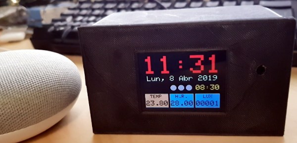
 But we can assure you this ESP32 alarm clock created by [Pangodream] is absolutely not one of them. He’s packed an impressive number of features into this unassuming little timepiece, and it’s really an excellent example of how much these boards are capable of without breaking a sweat. From DIY touch sensors to the Android application used to configure the clock over the network, this project is overflowing with neat hardware and software tricks worth taking a closer look at.
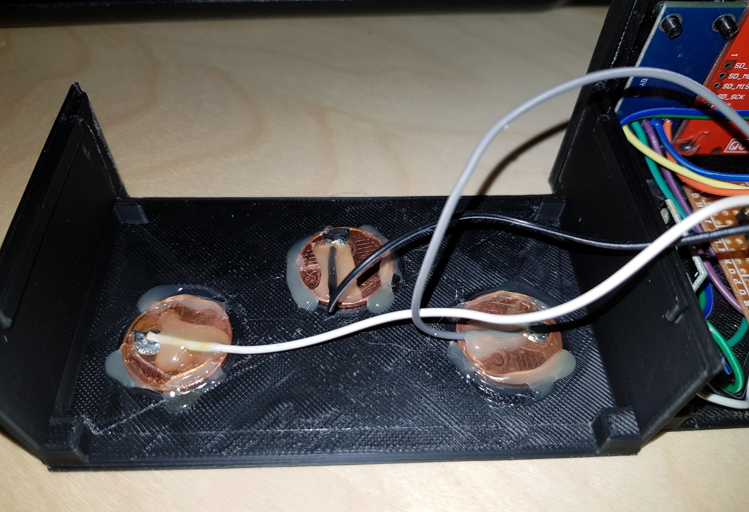
Inside the 3D printed case, the clock features a BH150 light sensor, the very popular DHT-11 for detecting temperature and humidity, as well as a ILI9341 2.8 inch LCD for the display. In a particularly clever touch (get it?), [Pangodream] used three coins connected to the digital pins of the ESP32 as capacitive sensors. These allow him to interact with the click just by tapping the top of the case, and saved him the trouble of adding traditional switches or buttons. We might have put some indentations in the top case to make identifying which of the three “buttons” you’re pushing, but we suppose the invisible interface does make things look a little more futuristic.
But if even that is too much physical touching for you, then [Pangodream] has come up with a fairly robust system for controlling and interacting with the clock over the network. It’s not just a convenient way of setting the time, a good number of the clock’s functions can be polled and configured in this manner; everything from the sensitivity of the touch sensors to how many times it will beep when the alarm goes off. To make things easier, he’s even wrapped it all up in a handy Android application for on the go configuration.
If this clock doesn’t offer you the level of over-engineering you require, check out this build that uses no less than five ESP32s to get the job done. Or maybe this one that hooks into NASA’s Deep Space Network.
Continue reading “ESP32 Alarm Clock Doesn’t Skimp On The Features” →
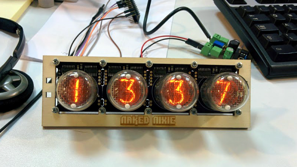

 If you mention a clock that receives its time via radio, most people will think of one taking a long wave signal from a station such as WWVB, MSF, or DCF77. A more recent trend however has been for clocks that set themselves from orbiting navigation satellites, and