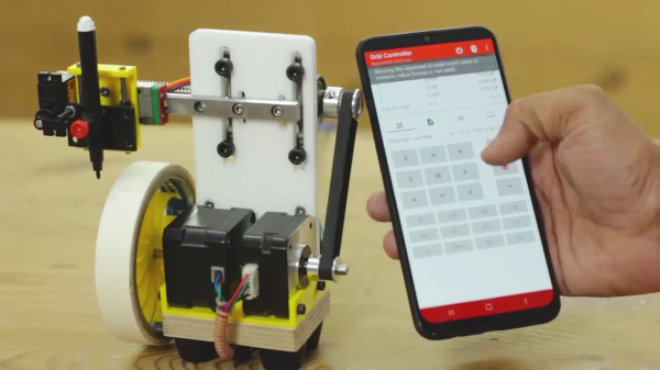
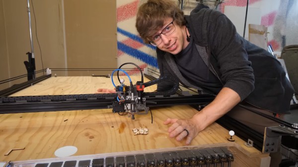
Pantographs were once used as simple mechanical devices for a range of tasks, including duplicating simple line drawings. [Tim] decided to make a modern electronic version that spits out G-Code instead.
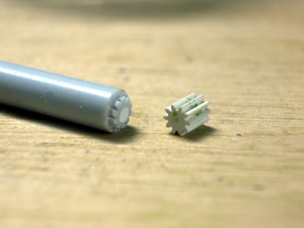
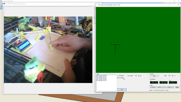
The design relies on a 3D-printed pantograph assembly, mounted upon a board as a base. A pair of Hall effect sensors are mounted in the pantograph, which, along with a series of neodymium magnets, can be used to measure the angles of the pantograph’s joints. The Hall sensors are read by an Arduino Nano, which computes the angles into movement of the pantograph head and records it as G-Code. This can simply be displayed on the attached LCD display, or offloaded to a computer for storage.
[Tim] explains the basic theory behind the work in an earlier piece, where he built a set of electronic dividers using the same techniques. He didn’t stop there, either. He also built a more complex version that works in 3D that he calls it the Electronic Point Mapper, which can be used to generate point clouds with a 3D-capable pantograph mechanism.
It’s a neat way to learn about geometry, and could even be useful if you’re doing some work in tracing 2D drawings or measuring 3D objects.
Continue reading “Tracing In 2D And 3D With Hall Effect Sensors”

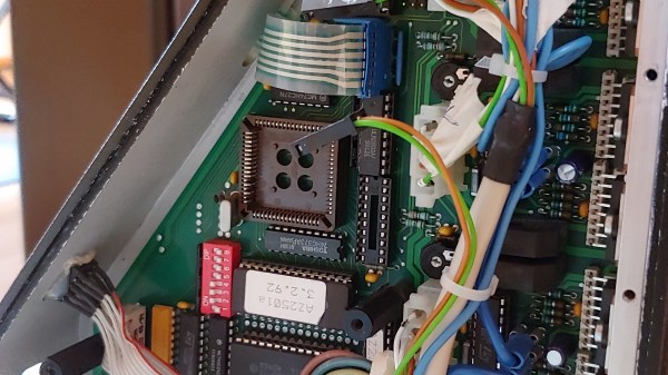
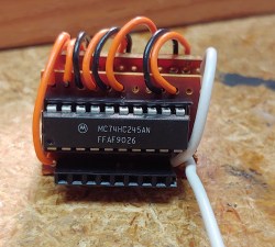 They reverse-engineered the motor driver connections – those go through a 74HC245 buffer between the original CPU and the drivers. Initially, they put an Arduino inside the control box of the CNC and it fit nicely, but it turned out the Arduino’s CPU would restart every time the spindle spun up – apparently, EMC would rear its head. So, they placed the Arduino out of the box, and used two CAT7 cables to wire up the motor and endstop signals to it.