According to [diyouware], inside of every HD-DVD player is a gem of laser engineering with the designation of PHR-803T, and it’s just begging to be converted into a PCB exposer. Following along similar hacks which tore the laser diode out of Blu-ray players to expose PCBs, they wanted to use the whole PHR-803T unit without disassembling it, and to try to enable all of its unique features.
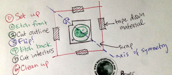
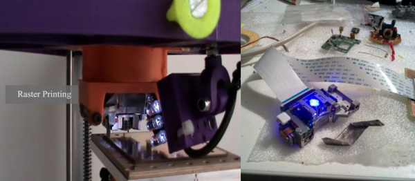
They envisioned something simple like a scanner for their machine. Just place the PCB on top of a glass sheet, close the lid, and click print. Unfortunately, moving the laser itself just caused too much vibration. So they switched to an inverted delta robot and named it TwinTeeth. In this design, the laser would stay still and the PCB would move.
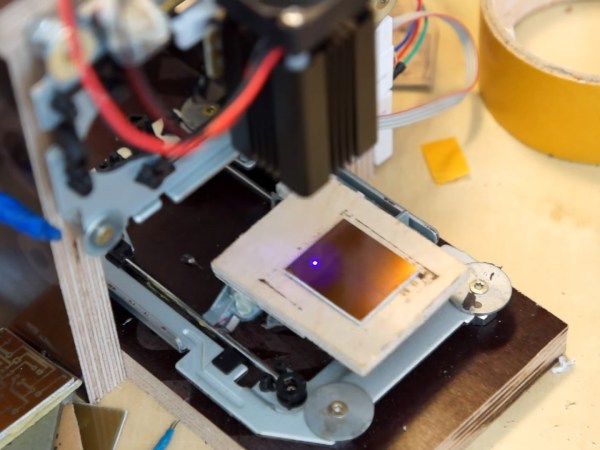
What follows next is a seriously impressive journey in reverse engineering and design. The PHR-803T had no data sheet, but a ton of features. For example, it can autofocus, and has three different laser diodes. So many interesting problems were found and solved. For example, the halo from the laser caused the surrounding photoresist to cure. They solved it by adding a glass plate with a UV filtering film on it. Only the most focused point of the laser could punch through.
Another adventure was the autofocus. They wanted to autofocus on all four corners of the board. The PHR-803T was designed to read HD-DVDs so can focus a beam to far below 0.01 mm. They got autofocus working with the UV laser, but couldn’t use it on the PCB without curing the photoresist. So they put a piece of aluminum foil at a known level to start. Then they realized they could use the red or infrared diodes to focus instead. Now they can level the PCB in software, and focus the diode without curing the photoresist.
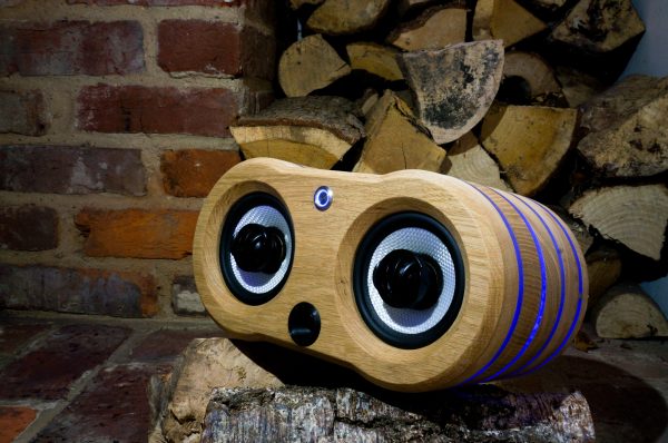
In the end they have an inverted-delta mini PCB factory. It can produce boards around the size of an Arduino shield with a resolution of 600 DPI. Their machine also has attachments for drilling and solder paste dispensing. Check out the video of it in action.
Continue reading “Take The Long Road To A Precise Laser PCB Exposer”