There is something refreshing about a neat, portable audio hack – especially one than involves making a DIY Speaker Box from scratch. [Dave] had some time to spare and his ShapeOko was lying idle and hankering for some attention. He needed a small speaker that he could place outside when entertaining guests. After some quick homework, he zeroed in on the speakers he would use.
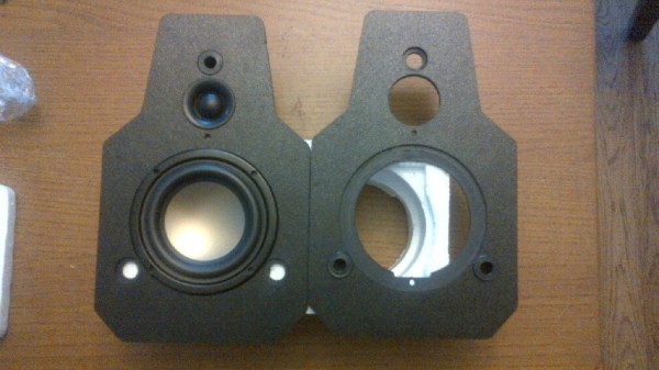
Using some online resources , he did some basic math to figure out the box size and shape, but then eventually threw caution to the wind and went ahead with the design he had in mind. Most speaker box builds use some form of wood or MDF. [Dave] had 9mm thick ABS sheets lying around and decided to use them instead. He used an interesting technique for putting the box together. The front and rear panels had slots milled in to them to follow the shape of the side panels. The two side panels had strategically cut slots half way through the thickness of the ABS to make it easier to heat bend them. He then used a heat gun to bend the side panels to fit them to the slots on the front and back panels. In the end, we’re guessing he used just four pieces of ABS to build a complex shape. Since the HiVi B3N speakers are full range, he also built a 1st order crossover to make sure the highs were diverted to the tweeters. All in all, a neat, clean build.