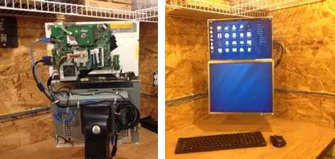
Fortifying Veronica’s VGA Output

[Quinn Dunki] just moved to a new work space and had to pack up her homebrew computer project — called Veronica — in the process. She just unboxed it again and decided now was a good time to fortify the VGA display hardware. It wasn’t in the greatest of shape, since everything for the initial video tests had been built on a breadboard. The transition to protoboard ended up turning out just swell.

One of the thing’s that we like best about [Quinn’s] hacks is that she documents her failures (or perhaps we should just call them hiccups?) just as much as she does her successes. This is not a small thing. We understand, because our own screw-ups don’t usually get photographed due to our raging need to just make the frakking thing work.

Once she had moved all the components to the new board the circuit was amazingly organized. Since she’s doing high-speed switching with the VGA signals it was important to keep the lines as short and straight as possible, hence the SRAM stack seen above. But when it was first fired up she had a jumble of only-somewhat-organized color stripes. It turns out that she had forgotten to change the color register in the AVR code, the color lines were hooked up in the wrong order, and the switch mode supply was injecting noise into the system. But thanks to her documentation of these issues we’ll know what to do when we find ourselves in a similar situation.

16-bit HCMOS Computer Is A Wire Wrapping Wonderland

The D16/M is a 16-bit computer built using HCMOS logic chips. It’s a thing of beauty from every angle thanks to the work [John Doran] put into the hobby project. But he didn’t just take pictures of the build and slap them on a webpage. He took the time to publish a remarkable volume of documents for the computer too!

The processor can execute a total of 73 instructions and offers a 100-pin bus for accessing main memory and peripherals. So far he has documented three different peripheral boards, each of which is pluggable thanks to an edge connector that accepts the board. The expansion boards are for system memory, serial communication port, and a clever four-position SD card interface for persistent storage.

Got a question about the system? He wrote a FAQ. Want to learn from his obvious mastery of wire-wrapping? He wrote a wire wrapping tips guide. Like we said, there’s a mountain of documentation and the links to it all are included in his main project page.

[Thanks Allen]

Computer Desk… Literally

This piece of furniture begs the question, why think of a desk and a computer case as separate things? It combines Ikea furniture with electronic hardware to create the ultimate command center.

First the obvious parts: there’s a nook for the computer case that hangs just below the desktop off to the side, and the twin displays are mounted front and center. The divider between the cabinet pieces was cut away to allow the monitors to be wall-mounted. But things start to get interesting to the left of those monitors. You can see a series of dial displays in the door for that cabinet. Those meters were sourced from the MIT Flea Market and after a bit of alteration they display CPU load information fed to them by  an Arduino board. This also drives some LED strips which are mounted behind the frosted glass panel that we guess could be called a back splash. The heavier the load, the better the light show.

All of the power management is taken care of in the cabinet to the right of the monitors. The top row hides a printer, external hard drive backup system, and several gaming consoles. Heat will be an issue so exhaust fans were added to each of these partitions. They’re switched based on a temperature sensor in each. It’s a lot of work, but the outcome proves it was worth it.

[via Reddit]

Bench Power Supply Resetting Thingy

As is common among some hackers, [Henry] re-purposed an ATX power supply unit to function as a bench power supply for testing circuits on a breadboard (much like this fancy example).

However, safety mechanisms on some modern PC PSUs do not automatically reset after over-current protection has kicked in, which soon became annoying for [Henry]. In order to make his power supply more hacker-friendly, he wired up and programmed an ATtiny85V, using some Arduino libraries, to do that for him. This simple project is a great example of using a hack to improve a pre-existing hack.

Raspberry Pi Finds Itself Inside A TRS-80 Model 100

This TRS-80 Model 100 is a lot more powerful than you might think. That’s because [Karl Lunt] is using it as an enclosure for his Raspberry Pi board. Since the ARM-powered device comes sans-enclosure it’s fun to see a retro choice like this one. And having had to go out and buy a USB keyboard to use our own RPi, we appreciate [Karl’s] solution for using the original keyboard as an input device.

Above you can see that he’s using an LCD tv as the display. For now that connection is made using the composite video output, which explains the fuzzy image. To the right of the TRS-80 a standard wall wart connects to the barrel jack to provide power. [Karl] scrapped a USB cellphone charger in order to connect from the barrel jack to the micro-USB jack on the Pi board. The ribbon cable to the left lets him get at the I/O header without opening the case.

In order to use the keyboard he patched into it with a Teensy board. That connects to the USB port on the RPi, sending HID keyboard commands based on what it received from the user. We like this option as it give you the ability to pre-process keystrokes (ie: you can code your own custom macros that the Teensy will listen for). Right now the Model 100’s LCD screen isn’t hooked up but he may add that in the future.

Pinball Stomp: Part 2

This is the 2nd and final part of this project. If you haven’t seen part 1 yet, jump back and check it out.

Now that we have the controller box made and ready to go, we just have to build some simple stomp sensors. As I said before, I doubt this will hold anyones attention longer than a night or two. With that in mind, I wanted to make this as cheaply and simply as possible.

To make these, you need the following:

  • Foam board or thick cardboard
  • aluminum tape
  • wire
  • duct tape

That’s it… no really, that’s it. Check out the video after the break to see how it all went, and what the kids thought of it.

Continue reading “Pinball Stomp: Part 2”

LED Case Lights Reflect CPU Usage

A lot of Linux users include system monitor information in their status panel so that they can see when the CPU is grinding away. [Kevin] is taking the concept one step further by changing his case lights based on CPU usage. Above you can see green, orange, and magenta, but [Kevin’s] implementation uses the full spectrum of color.

The project is based on an ATmega48. It’s running the V-USB stack and connects to one of the motherboard’s internal USB ports. This lets him easily push the CPU usage data over to the microcontroller where it is translated into color. One RGB LED has been installed behind each fan panel on the front of the case, with a white LED above and below as an accent. Pulse-width modulation via some MOSFETs lets him mix and match for just the right color. He’s powering the add-on off of the PSU rails rather than USB so that it turns off when the computer goes to standby.

Don’t miss [Kevin’s] explanation of the system, and a demo of it in action after the break.

Continue reading “LED Case Lights Reflect CPU Usage”