Microswitches: Past The Tipping Point

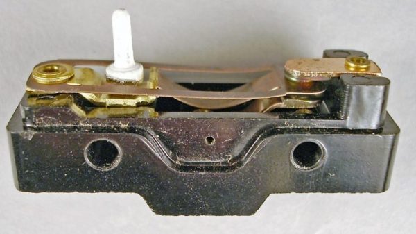
You find them everywhere from 3D printers to jet airliners. They’re the little switches that detect paper jams in your printer, or the big armored switches that sense when the elevator car is on the right floor. They’re microswitches, or more properly miniature snap-action switches, and they’re so common you may never have wondered what’s going on inside them. But the story behind how these switches were invented and the principle of physics at work in the guts of these tiny and useful switches are both pretty interesting.

Continue reading “Microswitches: Past The Tipping Point”

Say It With Me: Root-Mean-Square

If you measure a DC voltage, and want to get some idea of how “big” it is over time, it’s pretty easy: just take a number of measurements and take the average. If you’re interested in the average power over the same timeframe, it’s likely to be pretty close (though not identical) to the same answer you’d get if you calculated the power using the average voltage instead of calculating instantaneous power and averaging. DC voltages don’t move around that much.

Try the same trick with an AC voltage, and you get zero, or something nearby. Why? With an AC waveform, the positive voltage excursions cancel out the negative ones. You’d get the same result if the flip were switched off. Clearly, a simple average isn’t capturing what we think of as “size” in an AC waveform; we need a new concept of “size”. Enter root-mean-square (RMS) voltage.

To calculate the RMS voltage, you take a number of voltage readings, square them, add them all together, and then divide by the number of entries in the average before taking the square root: \sqrt{\frac{1}{n} \left(v_1^2 + v_2^2 +...+ v_n^2\right)} . The rationale behind this strange averaging procedure is that the resulting number can be used in calculating average power for AC waveforms through simple multiplication as you would for DC voltages. If that answer isn’t entirely satisfying to you, read on. Hopefully we’ll help it make a little more sense.



Continue reading “Say It With Me: Root-Mean-Square”

Hackaday Trims Its Own Resistors

There are times when you might want an odd-value resistor. Rather than run out to the store to buy a 3,140 Ω resistor, you can get there with a good ohmmeter and a willingness to solder things in series and parallel. But when you want a precise resistor value, and you want many of them, Frankensteining many resistors together over and over is a poor solution.

Something like an 8-bit R-2R resistor-ladder DAC, for instance, requires seventeen resistors of two values in better than 0.4% precision. That’s just not something I have on hand, and the series/parallel approach will get tiresome fast.

Ages ago, I had read about trimming resistors by hand, but had assumed that it was the domain of the madman. On the other hand, this is Hackaday; I had some time and a file. Could I trim and match resistors to within half a percent? Read on to find out.

Continue reading “Hackaday Trims Its Own Resistors”

Tracking Index Test

In an earlier article, I covered Fire Hazard Tests that form an important part of safety testing for electronic/electrical products. We looked at the standards and equipment used for abnormal heat, glowing wire and flame tests. A typical compliance test report for an appliance, such as a toaster, will be a fairly long document reporting the results for a large number of tests. Among these, the section for “Heat and Fire” will usually have the results of a third test – Tracking. It’s a phenomena most of us have observed, but needs some explanation to understand what it means.

What is Tracking ?

Tracking is a surface phenomena on an insulating material. When you have two conducting terminals or tracks at a high voltage (higher than 100 VAC) separated by an insulator, a combination of environmental factors such as dust, moisture and thermal cycling could cause minute leakage currents to flow on the surface between the conductors. Over time, the deposits carbonize and the surface current increases. Eventually, a carbon track forms over the surface of the insulator making it conductive at a particular “tracking” voltage. Finally, a short circuit is created between the two conductors which may also lead to fire. Worse, it’s possible that the tracking current could be lower than the rating of the protective fuse in the appliance, which will prevent the electrical supply from being cut off, creating a fire hazard. Tracking can be avoided by using the right kind of insulating materials and adequate creepage and clearance distances. One of the reasons for adding a slot between adjacent high voltage terminations or tracks on a PCB is to take care of tracking.

Test Standards

It’s impossible to conduct such tests according to real world conditions, so a standardized procedure is needed which can produce results that allow different materials to be compared. The IEC’s Technical sub-committee 15E was previously entrusted with the work of creating and maintaining tracking index methods and standards. Considering the importance of this standard and its wide implications, this work is now handled by TC 112 — Evaluation and qualification of electrical insulating materials and systems.

TC 112’s document IEC 60112 defines a “standardized method for the determination of the proof and the comparative tracking indices of solid insulating materials” for voltages up to 600 VAC, and provides information on how to design a suitable test equipment. The ASTM has an equivalent document — ASTM D3638 as does the UL — UL 746A-24. A more severe test is covered under IEC 60587 — “Electrical insulating materials used under severe ambient conditions – Test methods for evaluating resistance to tracking and erosion”. This test is often referred as the inclined plane tracking and erosion test and specifies test voltages up to 6 kV. But for now, let’s just look at the low voltage test as per IEC 60112.

Procedure

A sample of at least 20 mm x 20 mm with a minimum thickness of 3 mm is required for testing, with a set of five samples being tested each time. If the test product cannot provide a sample of these dimensions, then tiles of the insulating material need to be specifically produced using the same moulding process as used in actual production. The sample is supported on a horizontal glass platform. Two chisel-edged platinum electrodes are placed over the sample, separated by a gap of 4 mm. A voltage adjustable between 100 to 600 VAC is applied to these electrodes. The electrodes weigh down on the sample with a force of 1 N via dead weights.

The electrical supply to the electrodes needs to be current limited. For all voltages between 100 V to 600 V, the short circuit current across the electrodes must be limited to 1 A. This is usually done by means of a series variable resistor (rheostat). In some equipment designs, the Variac (variable auto-transformer) for adjusting the voltage is mechanically coupled to the rheostat ensuring the short circuit current is always limited to 1 A. An additional, smaller value rheostat is used for minor trimming. The standard further specifies that after setting the open circuit voltage, the measured voltage at 1 A current should not drop by more than 10% (load regulation). This makes transformer design a bit tricky. At low voltages, there isn’t enough magnetic coupling between the windings, causing higher drops at lower voltages. One solution is to use two secondary windings of about 350 V each which are connected in parallel for test voltage below 300 V, and in series for higher voltages. But there are other ways of satisfying this requirement too. It’s just one example of how the designer needs to look at every requirement in the standard and then figure out how to implement it in the test equipment.

The short-circuit current is just a limiting requirement of the electrical source connected to the electrodes. The more critical setting is the “tripping” current which needs to be set to 0.5 A above which the source must be disconnected from the electrodes. The tripping sensor needs to have a time delay of two seconds before it trips and the reason for this setting will become clear a bit later.

Environmental contamination is simulated by a salt solution — usually ammonium chloride having a concentration of 0.1%. An alternate solution is prescribed for more stringent testing. While applying the test voltage across the electrodes, one drop of the electrolyte is dropped over the test sample between the electrodes every 30 seconds for a total of 50 drops. The size of each drop needs to be adjusted such that 50 drops weigh roughly 1.075 grams and 20 drops weigh 0.430 grams. This can be achieved by careful selection of the needle diameter used for the drops as well as the delivery mechanism. Some designs use a gravity feed, solenoid operated device while others use a peristaltic pump. Another way is to use an air pump which forces the liquid out of its container by forcing air in to it. The test sample passes if it survives 50 drops without triggering the over current sensor. The sample fails if the over-current sensor gets triggered or if it catches fire, at which point the electrical supply needs to be disconnected immediately.

When a drop falls over the sample across the electrodes, most of the electrical current flows through the liquid since it is conductive. This causes a current spike that quickly boils off most of the salt solution, and generally lasts for a second or two. During this two-second duration, the over-current device is programmed not to trip. With most of the water having evaporated, some of the salt is left behind as a deposit over the sample, which causes “tracking” current to flow over its surface. A while later, you will also notice some scintillation effect (sparking) as the leftover salt crystals burn out when the current flows through them.

The results of a tracking test are reported in two different ways. A Proof Tracking Index test (PTI) is usually carried out at 175 V to confirm that the sample can survive 50 drops. On the other hand, a Comparative Tracking Index test is performed over a range of voltages, incrementing the test voltage by 25 V for each succeeding test. The number of drops is always set at 50. The CTI value is determined as the highest voltage at which the sample withstands 50 drops. In some cases, the sample must also pass the test at 25 V less than the CTI voltage for a duration of 100 drops. Depending on the CTI value, the insulator is assigned a Performance Level Category with PLC0 being the highest and PLC5 being the lowest.

It’s always fascinating looking at a sample undergoing the Tracking Index Test — check out the video below. When you look at data sheets for plastic materials, the Tracking Index value will always be reported under it’s electrical properties. Paper Phenolic, which was the PCB substrate used before the advent of fibreglass, usually has a very low tracking index value (depending on its composition), ranging between 100 V to 175 V. On the other hand, depending on composition and filler materials, fibreglass substrates such as FR4 can have CTI values ranging from 175 V up to about 300 V or higher.

If you have ever seen a PCB (not the components on it), give off Magic Smoke, then you’ve seen the effects of Tracking in action. With good design, taking into consideration proper creepage and clearance distances, it is one of the failure modes which can be prevented.

Continue reading “Tracking Index Test”

The Shocking Truth About Transformerless Power Supplies

Transformerless power supplies are showing up a lot here on Hackaday, especially in inexpensive products where the cost of a transformer would add significantly to the BOM. But transformerless power supplies are a double-edged sword. That title? Not clickbait. Poking around in a transformerless-powered device can turn your oscilloscope into a smoking pile or get you electrocuted if you don’t understand them and take proper safety precautions.

But this isn’t a scare piece. Transformerless designs are great in their proper place, and you’re probably going to encounter one someday because they’re in everything from LED lightbulbs to IoT WiFi switches. We’re going to look at how they work, and how to design and work on them safely, because you never know when you might want to hack on one.

Here’s the punchline: transformerless power supplies are safely useable only in situations where the entire device can be enclosed and nobody can accidentally come in contact with any part of it. That means no physical electrical connections in or out — RF and IR are fair game. And when you work with one, you have to know that any part of the circuit can be at mains voltage. Now read on to see why!

Continue reading “The Shocking Truth About Transformerless Power Supplies”

How Many Parts In A Triumph Herald Heater?

This Herald is in much better condition than my 12/50 was. Philafrenzy [CC BY-SA 4.0]
What was your first car? Mine was a 1965 Triumph Herald 12/50 in conifer green, and to be frank, it was a bit of a dog.

The Triumph Herald is a small saloon car manufactured between about 1959 and 1971. If you are British your grandparents probably had one, though if you are not a Brit you may have never heard of it. Americans may be familiar with the Triumph Spitfire sports car, a derivative on a shortened version of the same platform. It was an odd car even by the standards of British cars of the 1950s and 1960s. Standard Triumph, the manufacturer, had a problem with their pressing plant being owned by a rival, so had to design a car that used pressings of a smaller size that they could do in-house. Thus the Herald was one of the last British mass-produced cars to have a separate chassis, at a time when all other manufacturers had produced moncoques for years.

My 12/50 was the sporty model, it had the high-lift cam from the Spitfire and a full-length Britax sunroof. It was this sunroof that was its downfall, when I had it around a quarter century of rainwater had leaked in and rotted its rear bodywork. This combined with the engine being spectacularly tired and the Solex carburetor having a penchant for flooding the engine with petrol made it more of a pretty thing to look at than a useful piece of transport. But I loved it, tended it, and when it finally died irreparably I broke it for parts. Since then I’ve had four other Heralds of various different varieties, and the current one, a 1960 Herald 948, I’ve owned since the early 1990s. A piece of advice: never buy version 0 of a car.

Continue reading “How Many Parts In A Triumph Herald Heater?”

An Introduction To Differential I²C

A few weeks back, we talked about the no-nos of running I²C over long wires. For prototyping? Yes! But for a bulletproof production environment, this practice just won’t make the cut. This month I plucked my favorite solution from the bunch and gave it a spin. Specifically, I have put together a differential I²C (DI²C) setup with the PCA9615 to talk to a string of Bosch IMUs. Behold: an IMU Noodle is born! Grab yourself a cup of coffee and join me as I arm you with the nuts and bolts of DI²C so that you too can run I²C over long cables like a boss.

What’s so Schnazzy about Differential Signals?

There’s a host of ways to make I²C’s communication lines more noise resistant. From all of the choices we covered, I picked differential signals. They’re simple, fairly standardized, and just too elegant to ignore. Let’s take a moment for a brief “differential-signals-101” lecture. Hopefully, you’re already caffeinated! Continue reading “An Introduction To Differential I²C”