
This week’s Hacklet is all about Hackaday.io projects which use MIDI, or Musical Instrument Digital Interface for the uninitiated. MIDI was designed from the ground up as an open communications standard for musical instruments. Nearly every major instrument company participated in the design of the standard. MIDI was first demonstrated in January of 1983, with the communications standard document following in August. Hackers, makers, and musicians immediately ran with it, using MIDI to do things the designers never dreamed of.
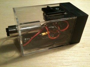
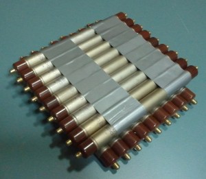 [Robert’s] 9×9 Pixel Muon Detector/Hodoscope is a great example of this. [Robert] is using 18 Geiger Muller Tubes to detect cosmic particles, specifically muons. The tubes are stacked in two rows which allows him to use coincidence detection. Rather than just plot some graphs or calculate impact probabilities, [Robert] hacked a Korg Nanokey 2 MIDI controller to output MIDI over USB messages corresponding to the detected muons. Check out his video to see a sample of the music of the universe!
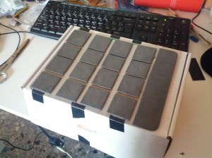 Next up is [Michele’s] DIY MPC style MIDI controller. [Michele] needed a simple low-cost drum controller that wouldn’t wake his neighbors. He loved Akai MPC controllers, so he rolled his own. [Michele] investigated force sensitive resistors but found they were very expensive. At a cost of $8 USD each, his resistors alone would be nearly the cost of a low-end MPC! [Michele] created his own sensitive pads using a sandwich of copper tape and 3M Velostat conductive sheets. An HCF4067 routes all the analog lines to a single pin of Teensy 3.0, which then converts the analog resistor outputs to MIDI messages.
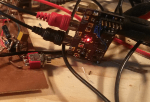 [Johan] loves his analog synths, and wanted them to be able to talk MIDI too. He built MIDI2VC, a circuit which converts MIDI to 1V/Octave (similar to CV/Gate). 1V/Octave is an analog control system used in some early synthesizers, as well as many modern analog creations. Pitches are assigned voltages, and as the name implies, each octave is 1 volt. A4 on the keyboard is represented by 4 volts, while A5 is 5 volts. [Johan] used a Microchip PIC16LF1823 to receive and convert the MIDI signals. The PIC outputs I2C data to an MCP4725 DAC which drives the analog side of the house.
 Long before DMX512 came on the scene, hackers were controlling lights via MIDI. [Artis] continues this with El Dance, a wireless system for controlling electroluminescent wire worn by dancers. Similar in function to [Akiba’s] EL wire system, [Artis] took a lower cost route and used the venerable NRF24L01 radio module. He added an antenna which gives the modules a range of about 30 meters. The computer running the dance routine’s music sees the transmitter side of the link as a MIDI instrument. Standard note on and off commands activate the EL wire strings.
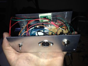 Our final hack comes from [Jen] who built a MIDI Vibrator Inductor Synth. [Jen] performs in an experimental music band called My Wife, with instruments as varied as violins and sewing machines. [Jen] must be a fan of Van Halen’s Poundcake as she’s using a similar technique, with a MIDI twist. An Arduino converts MIDI notes to analog values, which are sent to a motor controller board. The motor controller uses PWM to drive a vibrator motor at the frequency of the note being played. Like all DC motors, the vibrator puts out a ton of electromagnetic noise, which is easily picked up by [Jen’s] electric bass.
That’s it for this week’s Hacklet! Tune in next week for more projects from Hackday.io!

 Not all drones are multirotors – Posing in our title photo are
  P: This is the “Present” parameter. P Has the most influence on the behavior of the aircraft. If the wind blows your quadcopter from level flight into a 30 degree right bank, P is the term which will immediately take action to level the quad out. If the P value is too high, The quadcopter will overshoot level flight and start banking the other way. In fact, way too high a P value can cause a quadcopter to shake as it oscillates or “hunts” for level. Too Low a P value? the quadcopter will be very slow to react, and may never quite reach level flight again.
 a build. In this case it was 2.5mm banana plugs and motor mounting screws.
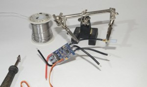 Bullet connectors can be a real pain to solder. There are some jigs out there which help, but I’ve always found myself going back to the old “helping hands” alligator clips. Bullets tend to use lower gauge wire than we’re used to with regular electronics. 14, 12, even 8 gauge wires are used on R/C aircraft. A low power soldering iron with a surface mount tip just won’t cut it. Those irons just doesn’t have the thermal mass to get the connectors up to soldering temperature. This is one of those places where a decent 40 watt or better Weller iron (yes, the kind that plugs right in the wall) can be a godsend. I’m using an Metcal iron here, with a wide flat tip.
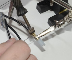 Bare bullet connectors and alligator clips can also create a problem – the metal clips create even more thermal mass. Years back an old-timer showed me a trick to handle this. Slip a piece of silicone R/C plane fuel tubing on the bullet, and then clip the helping hands onto the tube. The tube will act as insulation between the bullet and the clip. Silicone can easily withstand the temperatures of soldering. I’ve also used the silicone tube on the jaws themselves – though eventually the jaws will cut the soft tubing.