The business card is an odd survivor from the past, when you think about it. When a salesman in a Mad Men style suit stepped out of his Studebaker and walked past a room full of typists to the boss’s wood-paneled office, he would have handed over a card as a matter of course. It would get filed away in the Rolodex.
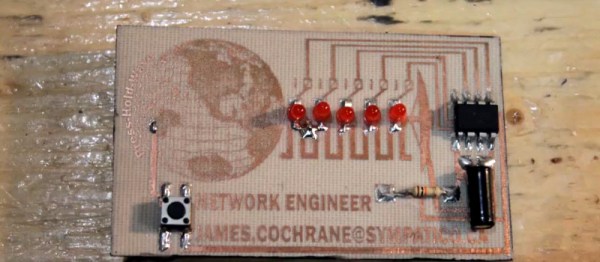
These days, making your card stand out from the crowd of print-shop specials has become an art form. In our community this extends to cards with integrated electronics, such as this one with a persistence-of-vision display driven by an ATtiny from [James Cochrane], shown in the video below. It’s by no means the first such card, but he takes us through its design and construction in great detail which makes the video below the break worth a look. If you have never made a toner transfer PCB for example, you can see how his was made.
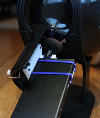
He makes the point that while a POV spinner needs only to display in one direction, a card has to be waved back and forth. Thus it needs to change the direction of its display, and needs a tilt sensor to activate this. His construction method uses through-hole components, but is surface mount in that they are soldered to the top surface of the board. The result is a rather attractive POV card that maybe isn’t something you’d hand out to all and sundry, but perhaps that’s not the point.