[Michael Lynch] has been a solo developer for over three years now, and has been carefully cataloguing his attempts at generating revenue for himself ever since making the jump to being self-employed. Success is not just hard work; it is partly knowing when the pull the plug on an idea, and [Micheal] has been very open about his adventures in this area. He shares the good news about a DIY project of his that ended up becoming a successful product, complete with dollar amounts and frank observations.
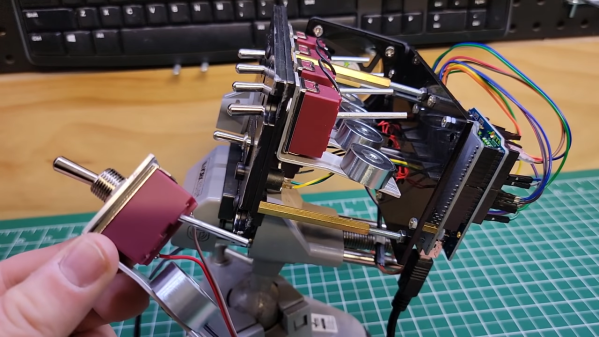
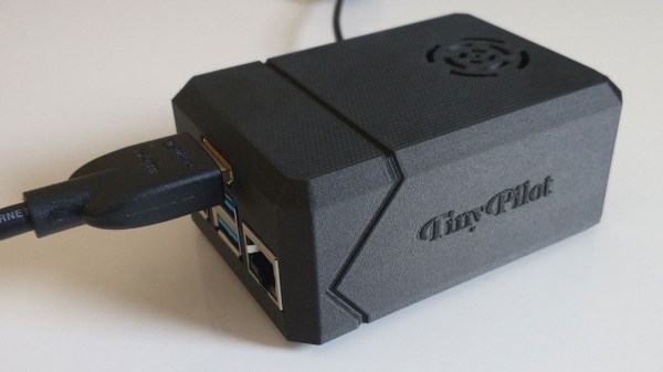
About a year ago, we covered a project he shared called TinyPilot, which is an effective KVM-over-IP device, accessible over the web, that could be built with about $100 worth of parts. [Micheal] found it to be a fun and useful project, and decided to see if he could sell kits. However, he admits he didn’t have high expectations, and his thoughts are probably pretty familiar to most hardware types:
I questioned whether there was a market for this. Why would anyone buy this device from me? It was just a collection of widely available hardware components.
Well, it turns out that he was onto something, and the demand for his device became immediately clear. He’s since given TinyPilot more features, an attractive case, and even provides a support plan for commercial customers. This is an excellent reminder that sometimes, what is being sold isn’t the collection of parts itself. Sometimes, what’s being sold is a solution to a problem people have, and those people are time-poor and willing to pay for something that just works.
It’s great to see [Michael] find some success as a solo developer, but his yearly wrap-up covers much more than just the success of TinyPilot as a product, so be sure to check it out if you’re at all interested in the journey of working for yourself.