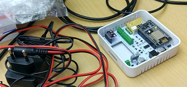
Once upon a time, small Linux-capable single board computers were novelties, but not anymore. Today we have a wide selection of them, many built around modules we could buy for our own projects. Some of the chipset suppliers behind these boards compete on cost, others find a niche to differentiate their product. Octavo Systems is one of the latter offering system-in-package (SiP) modules that are specifically designed for easy integration. They described how simple it would be to build a minimal computer using their SC335x C-SiP, and to drive the point home they brought a deadbug implementation to Embedded World 2019. [Short video after the break.]
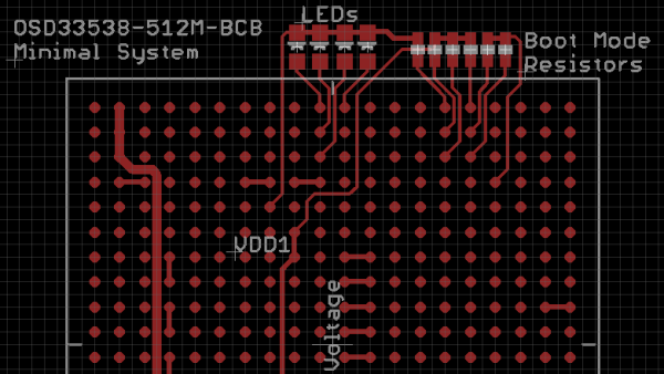
Most of us encounter Octavo modules as the heart of a BeagleBoard. Their increasing integration made tiny wonders like PocketBeagle possible. But bringing out all those pins for use still required a four-layer circuit board. Octavo’s pitch for hardware professionals center around how easy integration saves time for faster time to market, and fortunately for us easy integration also translates to a more accessible device for our projects. It’s one thing to publish a document describing a hypothetical single-layer PCB for an Octavo module, it’s quite something else to show that concept in action with no PCB at all.
Of course, this little machine only has access to a fraction of the module’s functionality, and it is certainly overkill if the objective is just to blink a few LEDs. If so, we’d just use 555 timers! But it does show how simple a bare bones “Hello World” machine can be built, removing intimidation factor and invite more people to come play.
We like blinky things. We’re moths drawn to the flame of serially-addressable RGB LEDs. If the LEDs are smaller, we want to know. If you can drive more of them, we want to know. That said, the most interesting news out of CES last January was both right up our alley, and immensely disappointing. Corsair, makers of RGB computer fans, RGB CPU coolers, and RGB keyboards and mice, have a new product out: RGB RAM, because professional gamers and streamers have a higher win percentage when their RAM is illuminated.
The key innovation of the new Corsair Dominator Platinum RGB DDR4 DRAM is called, ‘Capellix LEDs’. The press surrounding these LEDs gives a clear advantage: right now, the RGB LEDs in your gaming system are mounted in a large SMD package, like a WS2812 or APA101. These large packages reduce LED density, and making LEDs smaller means moar RGB — more colors, or brighter colors, or better efficiency. The key advancement in Capellix LEDs is taking the guts of a serially addressable RGB LED and putting it in a smaller package. Instead of a package that’s 2.8mm³ in volume, the Capellix LED is ‘just 0.2mm³ in size’. The few pictures available of these LEDs give the impression they’re about the size of an 0805 package. It’s small, and we’d like to get our hands on some.
Where these LEDs come from is anyone’s guess, but Corsair did partner with Primax, a Taiwanese manufacturer of computer peripherals, to pull this off. There is no mention of Capellix LEDs in Primax’s press releases, and we don’t actually know if these are the smallest serially addressable RGB LEDs available; we don’t even know if they’re serially addressable. There could easily be a small microcontroller in the Corsair Dominator Platinum RGB DDR4 DRAM, as each stick is only driving twelve individually controllable RGB LEDs.
The bottom line is, someone needs to spend $160 for 16GB of RAM, then tear the whole thing apart, preferably with close-up pics of the fancy new RGB LEDs.
A cynical reader would say that Capellix LEDs are simply existing LEDs, the name ‘Capellix’ was trademarked by Corsair, and these LEDs were shoved into a stick of RAM with a significant markup. This, surprisingly, is demonstrably wrong because there is no entry for ‘Capellix’ in the United States Patent and Trademark Office Trademark Electronic Search System. That doesn’t mean the spirit of the cynic is wrong, though; ROHM semiconductors just released a new side-view RGB LED that might be smaller than Corsair’s Capellix LEDs. There are, of course, RGB LEDs available in similar sizes, but none of these are serially-addressable like a WS2812 or APA101. We don’t know what’s in these fancy sticks of RAM, but we’re waiting for someone to do a tear down so we can find out.

For many, the Thinkpad T25 was something of a dream come true. Celebrating the 25th anniversary of the venerable business-oriented laptop that hackers love so much, it featured a design inspired by “retro” Thinkpads of yore, but with modern hardware inside. Unfortunately, as it was more fan service than a serious revitalization of classic Thinkpad design, the T25 was only ever available in a single hardware configuration.
[kitsunyan] liked the look and feel of the T25, but in 2019 was already feeling a bit let down by the hardware. The screen wasn’t up to snuff, and while the CPU is an i7, it only has dual cores. To make sure the T25 is still viable down the road, it seemed the only option was to try to transplant the hardware from one of the current Thinkpad models into the anniversary chassis. It certainly wasn’t easy, but given the fact that the T25 was more of a redress than a completely new product to begin with, everything came together a lot better than you might expect.
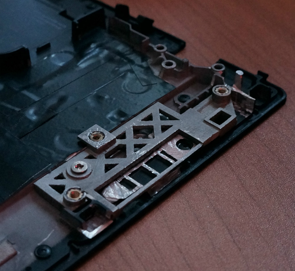
A custom mount installed in the T25
To help put things into perspective, the T25 is basically a modified version of the T470. Last year, Lenovo replaced the T470 with the new T480 that has just the sort of hardware improvements that [kitsunyan] wanted. The T480 was more of a refresh than a complete revamp, so the actual chassis of the machine didn’t change much compared with its predecessor. That being the case, it seemed like it should be possible to transplant the newer T480 components into the T470 derived T25. Got all that straight?
[kitsunyan] was able to put this theory to the test when the opportunity to connect a T25 keyboard to the newer T480 presented itself. Since the 7-row keyboard on the anniversary edition was one of its biggest selling points, seeing if it would work on another machine was kind of a big deal. It didn’t fit physically, and some of the keys didn’t work as expected, but it at least had the same connector and didn’t let out the magic smoke. It represented the first tiny step of a much larger journey.
In the end, it took a lot of trimming, gluing, hacking, and fiddling to get all the new hardware from the T480 to fit into the T25. But if you’re brave enough, the process has been detailed exquisitely by [kitsunyan]. Not only are the part numbers listed for everything you need to order, but there’s plenty of pictures to help illustrate the modifications that need to be made to all the clips, brackets, and assorted widgets that go into a modern laptop.
Firmware and software are both just code, right? How different could the code that runs Internet-scale distributed web stuff be from the code that runs a tiny microcontroller brain inside a personal hydroponics device? Night and day!
Ruth Grace Wong works in the former world, but moonlights as a manufacturing engineer with some friends. Their product had pre-existing firmware that contained (at least) one bug, and Ruth’s job was to find it. The code in question was written by the Chinese PCB engineer, who knew the electronics intimately but who had no software background, providing Ruth an opportunity to jump head-first into the rawest of raw embedded programming. Spoiler alert: she found the bug and learned a lot about firmware along the way. This talk follows her along the adventure.
“The code is very well documented, in Chinese” but the variable names are insanely non-descriptive. Similarly, while the PCB engineer knows full well what a 24C02 is, if you’re a software geek that might as well be Chinese. As you’d expect, web searches came to the rescue on both fronts.
The bug ended up hiding in a logical flaw in the PWM-setting code inside an interrupt service routine, and it kept the fan from ever coming full on. Once found, it was easily fixed. But getting to the point where you understand the codebase deeply enough to know where to look is four-fifths of the battle. Heck, setting up the toolchain alone can take a day or two.
If you’re a fellow software type, Ruth’s talk (embedded below) will give you a quick glimpse into the outer few layers of the onion that is embedded firmware development, from a familiar viewpoint. Give her quick and value-packed talk a watch! Grizzled hardware veterans will nod along, and maybe even gain a little insight into how our code looks to “them”.
For one reason or another, a lot of us have a bunch of 18650 cells sitting around. Whether they’re for flashlights, our fancy new vape pen, remote controlled toys, or something more obscure, there is a need to charge a bunch of lithium ion cells all at once. This project, by [Daren Schwenke], is the way to do it. It’ll charge ten 18650 cells quickly using a stock ATX power supply and less than twenty bucks in Amazon Prime parts.
The idea began when [Daren] realized his desktop lithium ion charger took between 4-6 hours to fully charge two 18650 cells. With a Mountainboard project, or a big ‘ol electric skateboard waiting in the wings, [Daren] realized there had to be a better solution to charging a bunch of 18650 cells. There is, and it’s those twenty bucks at Amazon and a few 3D printed parts.
The relevant parts are just a ten-pack of 18650 cell holders (with PC pins) and a ten-pack of 5V, 1A charging modules (non-referral Amazon link, support truly independent journalism) meant to be the brains of a small USB power bank. These parts were wired up to the 5V rail of a discarded ATX power supply (free, because you can scavenge these anywhere, and everything was wrapped up with a neat little 3D printed mount.
Is this the safest way to charge lithium ion cells? No, because you can build a similar project with bailing wire. There is no reverse polarity protection, and if there’s one thing you never want to do, it’s reverse the polarity. This is, however, a very effective and very cheap solution to charging a bunch of batteries. It does what it says it’ll do, nothing more.
Regular readers of Hackaday have certainly seen the work of [Jeremy Cook] at this point. Whether you remember him from his time as a writer for this fine online publication, or recognize the name from one of his impressive builds over the last few years, he’s a bona fide celebrity around these parts. In fact, he’s so mobbed with fans at events that he’s been forced to employ a robotic companion to handle distributing his personalized buttons for his own safety.
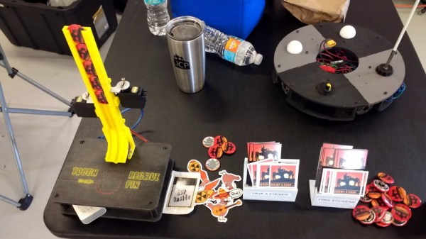
Alright, that might be something of a stretch. But [Jeremy] figured it couldn’t hurt to have an interesting piece of hardware handing out his swag at the recent Palm Bay Mini Maker Faire. Anyone can just put some stickers and buttons in a bowl on a table, but that’s hardly the hacker way. In the video after the break, he walks viewers through the design and construction of this fun gadget, which takes a couple unexpected turns and has contains more than a few useful tips which are worth the cost of admission alone.
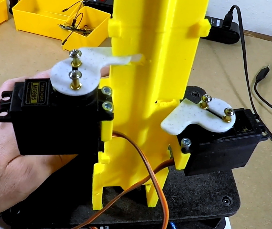
Outwardly the 3D printed design is simple enough, and reminds us of those track kits for Matchbox cars. As you might expect, getting the buttons to slide down a printed track was easy enough. Especially when [Jeremy] filed the inside smooth to really get them moving. But the goal was to have a single button get dispensed each time the device was triggered, but that ended up being easier said than done.
The first attempt used magnets actuated by two servos, one to drop the button and the other to hold up the ones queued above it. This worked fine…at first. But [Jeremy] eventually found that as he stacked more buttons up in the track, the magnets weren’t strong enough to hold them back and they started “leaking”. This is an excellent example of how a system can work perfectly during initial testing, but break down once it hits the real world.
In this case, the solution ended up being relatively simple. [Jeremy] kept the two servos controlled by an Arduino and a capacitive sensor, but replaced the magnets with physical levers. The principle is the same, but now the system is strong enough to hold back the combined weight of the buttons in the chute. It did require him to cut into the track after it had already been assembled, but we can’t blame him for not wanting to start over.
We all know CERN as that cool place where physicists play with massive, superconducting rings to smash atoms and subatomic particles to uncover secrets of matter in the Universe. To achieve this aim, they need to do a ton of research in other areas, such as development of special particle detectors.
While such developments are essential to the core research needs of the Centre, they also lead to spinoff applications for the benefit of society at large. One such outcome has been the Medipix Collaborations – a family of read-out chips for particle imaging and detection that can count single photons, allowing X-rays and gamma rays to be converted to electrical signals. It may not be possible for us hackers to get our hands on these esoteric sensors, but these devices are pretty interesting and deserve a closer look. Medipix sensors work like a camera, detecting and counting each individual particle hitting the pixels when its electronic shutter is open. This enables high-resolution, high-contrast, noise hit free images – making it unique for imaging applications.
Some months back, CERN announced the first 3D color X-ray of a human made possible using the Medipix devices. The result is a high-resolution, 3D, color image of not just living structures like bones, muscular tissues and vessels, but metal objects too like the wrist watch, seen in the accompanying photograph. The Medipix sensors have been in development since the 1990’s and are presently in their 4th “generation”. Each chip consists of a top semiconducting sensor array, made from gallium arsenide or cadmium telluride. The charge collected by each pixel is transported to the CMOS ASIC electronics via “bump bonds”. The integration is vertical, with each sensing pixel connected via the bump bond to an analog section followed by a digital processing layer. Earlier versions were limited, by technology, in their tiling ability for creating larger matrices of multiple sensors. They could be abutted on three sides only, with the fourth being used for on-chip peripheral logic and wire-bond pads that permit electronic read-out. The latest Medipix4 Collaboration, still under some development, eliminates this short coming. Through-silicon-via (TSV) technology provides the possibility of reading the chips through copper-filled holes that bring the signals from the front side of the chip to its rear. All communication with the pixel matrix flows through the rear of the chip – the peripheral logic and control elements are integrated inside the pixel matrix.
The Analog front end consists of a pre-amplifier followed by a window discriminator which has upper and lower threshold levels. The discriminator has four bits for threshold adjustment as well as polarity sensing. This allows the capture window to be precisely set. The rest of the digital electronics – multiplexers, shift registers, shutter and logic control – helps extract the data.
Further development of the Medipix (Tech Brief, PDF) devices led to a separate version called Timepix (Tech Brief, PDF). These new devices, besides being able to count photons, are capable of two additional modes. The first mode records “Time-Over-Threshold”, providing rough analog information about the energy of the photon. It does this by counting clock pulses for the duration when the signal stays above the discrimination levels. The other mode, “Time of Arrival”, measures arrival time of the first particle to impinge on the pixel. The counters record time between a trigger and detection of radiation quanta with energy above the discrimination level, allowing time-of-flight applications in imaging.
Medipix3 pixel schematic
Timepix2 pixel schematic
Besides medical imaging, the devices have applications in space, material analysis, education and of course, high energy physics. Hopefully, in a few years, hackers will lay their hands on these interesting devices and we can get to know them better. At the moment, the Medipix website has some more details and data sheets if you would like to dig deeper. For an overview on the development of such single photon detectors, check out this presentation from CERN – “Single X-Ray Photon Counting Systems: Existing Systems, Systems Under Development And Future Trends” (PDF).