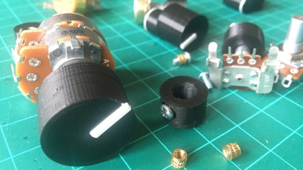
Rotary potentiometers, switches, and encoders all share a basic design: adjustment is done via a shaft onto which a knob is attached, and knobs are sold separately. That doesn’t mean one knob fits all; there are actually a few different standards. But just because knobs are inexpensive and easily obtained doesn’t mean it’s not worth making your own.
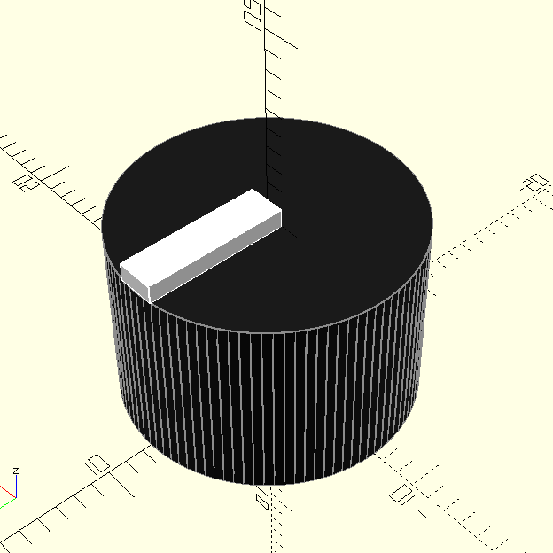
Why bother 3D printing your own knobs instead of buying them? For one thing, making them means one can rest assured that every knob matches aesthetically. The ability to add custom or nonstandard markings are another bonus. Finally, there’s no need to re-invent the wheel, because [Tommy]’s guide to making your own knobs has it all figured out, with the OpenSCAD script to match.
By default, [Tommy]’s script will generate a knob with three shims (for interfacing to a splined shaft) when pot_knob(); is called. The number of shims can be adjusted by modifying potKnobDefaultShimCount. To give the knob a flat side (to interface with D-shafts), change flatted = false to flatted = true. And for adding a screw insert suitable for a set screw? Change tightenerDiameter = 0 from zero to the diameter desired.
The script is quite comprehensive and has sensible defaults, but it does require a bit of knowledge about OpenSCAD itself to use effectively. We have covered the basics of OpenSCAD in the past, and if you’re ready for a resource that will help you truly master it, here’s where to look.