The trend in video games is toward not being able to differentiate them from live-action theatrical releases, and games studios are getting hard to tell from movie studios. But quality graphics don’t always translate into quality gameplay, and a lot can be accomplished with minimalist graphics. Turn the clock back a few decades and think about the quarters sucked up by classics like Pac-Man, Space Invaders, and even Pong if you have any doubts about that.
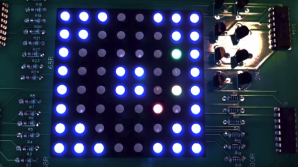
But even Pong had more than 64 pixels to work with, which is why this dungeon-crawler game on an 8×8 RGB matrix is so intriguing. You might think [Stolistic]’s game would be as simple as possible but think again. The video below shows it in action, and while new users will need a little help figuring out what the various colors mean, the game is remarkably engaging. The structure of the dungeon is random with multiple levels to unlock via the contents of power-up chests, and there are mobs to battle in a zoomed-in display. The game runs on an Arduino Uno and the matrix is driven by a bunch of 74HC595 shift registers.
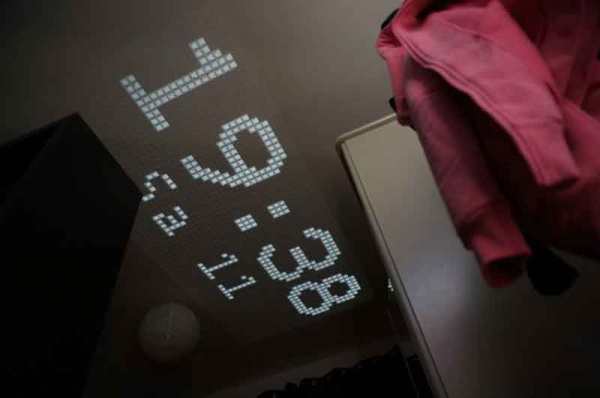
It’s fun to see what can be accomplished with as little as possible. Looking for more low-res goodness? Check out this minimalist animated display, or a Geiger counter with a matrix display.


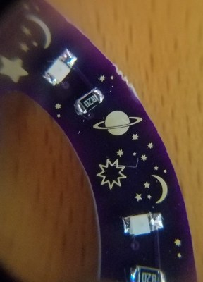 Don’t take that the wrong way, there’s still a lot of creativity that [Steve] over at Big Mess o’ Wires used to make it look this great. The key element here is that copper and solder mask placements have extremely fine pitch. After placing the LEDs and resistors there’s a lot of blank space which was filled with what you might see in the night sky through your telescope. What caught our eye about this badge is the fidelity of the ringed planet.