[Brainsmoke] had a simple plan. Make a quadcopter with lots of addressable LEDs.
Not just a normal quadcopter with ugly festoons of LED tape though. [Brainsmoke] wanted to put his LEDs in a ball. Thus was born the polyhedrone, the idea of a flying deltoidal hexecontahedron covered as you might expect with all those addressable LEDs.
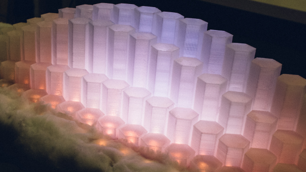
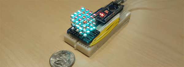
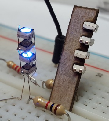
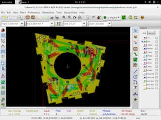 A Catalan solid makes a good choice for the homebrew polyhedron builder because its faces are all identical. Thus if you are making PCBs to carry LEDs, for example, you need only create a single PCB design to use on all faces. A bit of work in KiCAD, and a single face design with interlocking edges was ready. The boards were tested, a wiring layout was worked out, and the polyhedron was assembled.
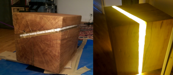
But [Brainsmoke] didn’t stop there. He produced a flight case for the polyhedron, in the form of a larger polyhedron from what looks like lasercut thin ply.
Having a finished polyhedron, the next thing was to hook up a Raspberry Pi and write some software. First in Python, then in Go.
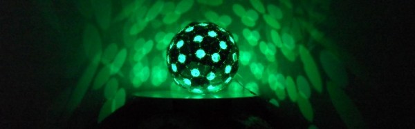
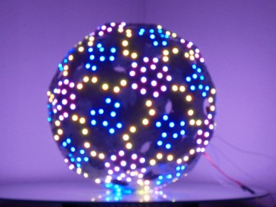 The results are simply stunning. If the mathematics and construction of a polyhedron were not enough to make this project worth a second look, then the gallery of images should be enough. You’ll notice that this is ostensibly a quadcopter project, yet no mention of flying has been made on this page. That’s because this is still a work in progress at Tech Inc Amsterdam, and there is more to come. But it honestly doesn’t matter if this project never moves a millimeter off the ground, as far as we are concerned [Brainsmoke] has created a superbly built thing of beauty in its own right, and we like that.
As you might expect, this is just the latest of many projects featured here that have involved addressable LEDs or quadcopters. Of note among them is this LED polyhedron that cleverly closes in all its bits, and this LED-equipped quadcopter that generates very pleasing patterns with a hi-res cross of pixels.