
For a recent event [Norwegian Creations] decided to make something fun. They built what might just be the tallest free-standing gravity pong game out there. It’s 4.5m tall, and the LEDs in it draw over 100 amps!
What is Gravity Pong anyway? Well it’s a single person game where you get three “bounces”. A ball of light will drop from the top of the tube and the closer to the bounce-line you hit the button, the higher it will bounce. Your high score consists of how high you get the light — but if you miss the bounce line, you lose!
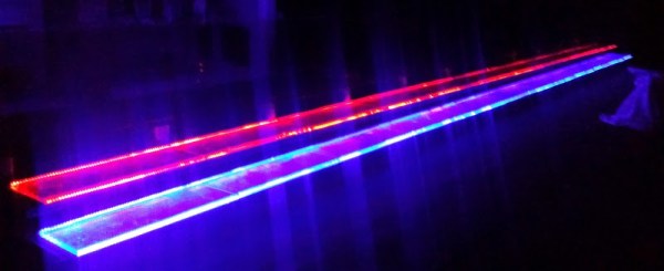
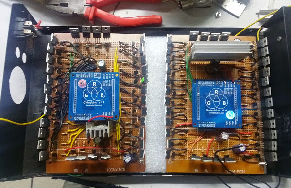
The structure itself is quite impressive. They’ve wrapped acrylic tubes with 1792 individually controllable RGB LEDs, in groups of four. Each section requires a power supply capable of putting out 27A @ 5V! The game is controlled by a Raspberry Pi 2 which controls a Pixelpusher to manipulate the LEDs. It’s connected to the Internet, so high scores can be automatically uploaded!
When it comes to pong though, we quite enjoy playing it with $5,000 construction crane controllers — because why not?


 The project took around 450 meters of RGB strips controlled by
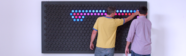
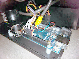 Behind the clock is an Arduino driving a MAX7219 LED controller. Using the MAX7219 was a challenge because it expects a grid of LEDs while the clock needs a linear array. [Dylan] used a line of individual LEDs wired to match what the controller wanted. A rotary encoder tells the processor the position of the arm so the Arduino sketch can determine which LEDs should be lit to show the time and clock face.


