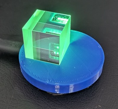
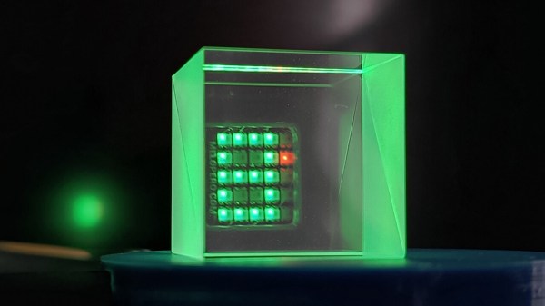
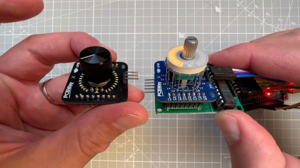
Exploded version of the Cistercian display

Serial Cistercian Digit Module

There’s no doubt that the 7-segment display is a gold standard for displaying lighted digits. But what about a throwback to an older system of displaying numbers — Cistercian? With thirty-one 0805 LEDs, [Josue Alejandro] made a simple module displaying a single Cistercian digit (any from 0-9999).

The first iteration used castellated edges and required a significant number of GPIO, so on the next rev, he switched to a serial-to-parallel converted from Lumissil (IS31FL3726A). A diffuser and spacer were printed from PLA and made for an incredibly snazzy-looking package.

Of course, it couldn’t stop there, and a third revision was made that uses SK6812 Neopixels, allowing full RGB capability. All the design documents, layout files, and incredibly detailed drawings are available on GitHub. What makes this incredibly handy is having a module you can easily add to a project. Perhaps even as a component in an escape room in a box that would allow you to flash multiple numbers. Or perhaps as a stylish clock. We’d even go so far as to challenge someone to create a calculator by combining several of these modules with this keypad.

photograph of custom PCB assembly of NE555-based electronic dice

NE555-Based Electronic Dice

It has become a bit of a running joke in the Hackaday community to suggest that a project could or should have been done with a 555 timer. [Tim] has rather taken this to heart with his latest Electronic Dice project, which uses three of the venerable devices.

If three seems like a lot of 555s to make an electronic die, then it may be worth considering that the last time we shared his project he was using 22 of them! Since then, [Tim] has been busy optimising his design, whilst keeping within the constraints of an old-school through-hole soldering kit.

Maybe the most surprising thing about this project is the purpose to which the NE555 devices are pressed. Rather than using them for their famous oscillation properties, they are in actual fact just being used as Schmitt Triggers to clean up the three-phase ring oscillator that is constructed from discrete transistors and passives.

scope trace of the electronic dice ring oscillator
Simulation trace of the three-phase ring oscillator before Scmitt Trigger stages

The ring oscillator cleverly produces three phase-shifted square waves such that a binary combination of the three phases offers six unique states. Six being the perfect number for a dice throw, all that then remains is to figure out which LEDs need to be switched on in which state and wire them up accordingly.

To “roll” the dice, a push-button powers up the oscillator, and stops it again when it is released, displaying the random end-state on the LEDs.

It can be fun to see what can be done using old technology, and educational to try to optimise a design down to the fewest parts possible.

[Tim]’s earlier project is here if you want to see how the design has evolved. The documentation on both of these iterations is excellent and well worth a read.

Continue reading “NE555-Based Electronic Dice”

tiny surface mount seven segment display

Nano-Sized 7-Segment LED Display On A Surface Mount Module

Inspired by a prank tweet, [Sam Ettinger] endeavored to create an SMD seven-segment display.  The NanoRaptor NanoSegment implements a panel of seven-segment display modules sized at “0806” each or just a bit wider than a standard 0805 SMD footprint.  Each of the seven segments is a single 0201 LED.  Six I/O lines and three resistors are required to operate each module.

To demonstrate the operation of his tiny display modules, Sam also created the “6Pin 7Seg” development board featuring an ATtiny84 microcontroller coupled to PCB footprints sized to receive the NanoRaptor NanoSegment display modules.  A demonstration of the board counts through digits displayed on one of the tiny seven-segment modules.

Hoping to reduce the module’s interface to two pins, Sam is now experimenting with a seven-segment display on a flex PCB that folds up into a 1208 footprint.  He is attempting to fold the resistors and a ATtiny20 microcontroller into an “origami PCB” configuration.

If these hacks are getting a little too small for your tastes, we’ve got you covered with this giant seven-segment display.


Turn Your Furniture Into A Light Show With Hyelicht

There’s something about the regimented square shapes of the IKEA Kallax shelf that convinced [Eike Hein] it could benefit from some RGB LED lighting, and while he could have simply used a commercial solution, he decided instead to develop Hyelicht: an incredibly well documented open source lighting system featuring multiple control interfaces and APIs. We’d say it was overkill, but truth be told, we dream of a world where everyone takes their personal projects to this level.

Hyelicht’s default touch UI

In the boilerplate configuration, [Eike] shows off controlling the LEDs using a graphical user interface running on a Waveshare 7″ touch screen mounted to the side of the shelf. That’s the most direct way of controlling the LEDs, as the touch screen is plugged into the Raspberry Pi 4B that’s actually running the software. But the same interface can also be remotely accessed by your smartphone or desktop.

You can also skip the GUI entirely and control the LEDs with a command line interface, or maybe poke Hyelicht’s HTTP REST interface instead. The system can even integrate with the Philips Hue ecosystem, if you prefer going that route.

The 5×5 Kallax shelf is the project’s official reference hardware, but of course it will work with anything else you might wish to cover with controllable LEDs. We’ve seen similar setups used to light storage bins in the past, but nothing that can even come close to the documentation and customization possibilities offered by Hyelicht. This is definitely a project to keep a close eye on if you’ve got the urge to add a little color to your world.

A two picture montage of a boy wearing a sonic the hedgehog costume with LEDs in them. The left picture is at night with the boy wearing sunglasses and a face mask with the sonic costume head piece lit up. The right picture is during the day with the boy wearing a face mask, holding a plastic pu mpkin bucket for candy and wearing a lit up sonic the hedgehog costume in the front yard of a house.

LEDs Put New Spin On A Sonic The Hedgehog Costume

[Wentworthm] couldn’t say no to his son’s plea for a Sonic the Hedgehog costume for Halloween but also couldn’t resist sprucing it up with LEDs either. The end result is a surprisingly cool light up Sonic the Hedgehog costume.

a picture of a breadboard with an Arduino Nano on it, with wires going out to 3d printed tear dropped shapes that have LED strips in them, with some LED strips on.

After some experimentation, [Wentworthm] ordered two costumes and ended up mixing and matching the head piece of one with the body suit of the other. For the head, [Wentworthm] created six 3D printed “quills” that had slots for the WS2812B LED strips to slide into and diffuse out the sides, with each quill sliding into the folds of the Sonic head “spikes”. Sewn strips of cloth were used to house the LED strips that were placed down the sides of the costume. An additional 3D printed switch housing was created to allow for a more robust interface to the two push buttons to activate the LEDs. An Arduino Nano, soldered to a protoboard, was used to drive the LED strips with a USB battery pack powering the whole project.

[Wentworthm] goes into more detail about the trials and errors, so the post is definitely worth checking out for more detail on the build. Halloween is always a great source of cool costumes and we’ve featured some great ones before, like a light up crosswalk costume to making a giant Gameboy colour costume.

Video after the break!

Continue reading “LEDs Put New Spin On A Sonic The Hedgehog Costume”

Homebrew LED Bulbs Keep Your Circadian Rhythms Steady

There was a time when LED light bulbs were a premium product that commanded a premium price, mainly because of limited supply and the usual marketing tricks. But now is not that time, since you can pick up an LED bulb for a buck or two at pretty much any store. So why in the world would you go to the effort to make your own light bulb?

For [DiodeGoneWild], the answer is simple: it’s all about staying in rhythm. Circadian rhythm, that is. We all know how light toward the blue end of the spectrum is bad for our sleep cycle, since it convinces our lizard brain that dawn is at hand. But even if you pick an LED bulb with a warm, or reddish, color temperature, there’s still a lot of UV light being emitted thanks to the phosphor LEDs that are typically used in them.

[DiodeGoneWild]’s first attempt at a design, in the first video below, mostly avoids phosphor LEDs in favor of a mix of yellow, red, and yellow-green LEDs to get a warmer spectrum. He used the housing and base from an expired bulb to enclose his custom circular PCB, the fabrication of which using a hand drill as a lathe and a Dremel to machine concentric tracks in the cladding was a real treat. So was the power supply, for that matter — a dropping capacitor followed by a bridge rectifier and a filtering cap. We like the discharge resistors across the caps and the fusible resistor on the mains side — it’s nice to see safety factored in from the start. And what’s not to like about using a DVD as a makeshift spectroscope?

We see that [DiodeGoneWild] has just dropped a second design, this time in a much smaller bulb and with relatively more phosphor LEDs.

Continue reading “Homebrew LED Bulbs Keep Your Circadian Rhythms Steady”

Tidy POV Display Using The ESP32

Chinese Youtuber [corebb] presents the second version of his POV display. The earlier version used 5050-sized SMT addressable LEDs, which didn’t give great resolution, so he rev’d the design to use a much higher number (160 to be exact) of APA102 LEDs. These are 2mm on the side, making them a little more difficult to handle, so after some initial solder paste wobbles, he decided to use a contract assembly house to do the tricky bit for him. This failed as they didn’t ‘understand’ the part and placed them the wrong way around! Not to be deterred, he had another go with a modified solder stencil, and eventually got the full strip to light up correctly.

Based on an ESP32 (using the Arduino stack) and SDCard for control, and a LiPo cell charged wirelessly, the build is rather tidy. A couple of hall effect switches are mounted at the start of each of the two arms, presumably lining

Real-time video streaming? Check!

up with a magnet on the case somewhere, although this isn’t clear. The schematic and PCB appear to have been designed with JLCEDA, which is a repackaging of EasyEDA. We can see the attraction with the heavy integration of this with the JLC and LCSC services. It appears that he even managed to get streamed video working — showing a live video from a webcam — which is quite an undertaking to pull off when you think how much processing needs to happen in real-time. As he alludes to in the video, trying to increase the resolution beyond this point is not viable with the processing capability of the ESP32.

A resin-printed case finishes off the build, with a screw-thread mount added to the rear, to allow typical camera mounts to be used to hold the thing down. A smart move we think.

We love POV displays around here, this spherical POV display is especially fabulous, but you don’t need fancy hardware if you have a handy ceiling fan and a bit of protoboard spare.

Continue reading “Tidy POV Display Using The ESP32”