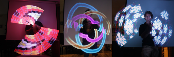
The human body does plenty of cool tricks, but one of the easiest to take advantage of is persistence of vision (POV). Our eyes continue to see light for a fraction of a second after the light goes off, and we can leverage this into fun blinkenlight toys like POV staffs. Sure, you can buy POV staffs and other devices, but they’re pretty expensive and you won’t learn anything that way. Building something yourself is often the more expensive route, but that’s not the case with [shurik179]’s excellent open-source POV staff.
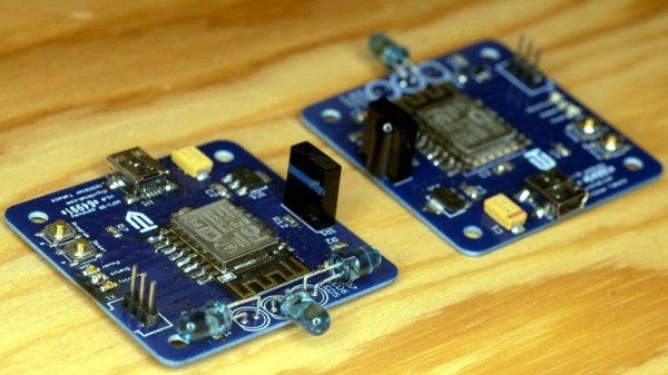
There’s a lot to like about this project, starting with the detailed instructions. It’s based on the ItsyBitsyM4 Express and Adafruit’s Dotstar LED strips. You could use the Bluetooth version, but it’s already quite easy to load images to the staff because it shows up as a USB mass storage device. We like that [shurik179] added an IMU and coded the staff so that the images look consistent no matter how fast the staff is spinning. In the future, [shurik179] might make a Bluetooth version that’s collapsible. That sounds like quite the feat, and we can’t wait to see it in action.
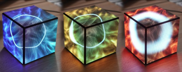
As cool as it is to wave a POV staff around, there’s no real practical application. What’s more practical than a clock?