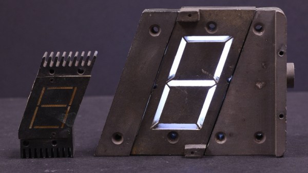
When [Patrick Hickey] spent a tidy sum on eBay to purchase a pair of seven-segment displays used in the Launch Control Center at Kennedy Space Center during the Apollo program, he could have just put them up on a shelf. It’s certainly what most people would have done. Instead, he’s decided to study and document their design with the hope of eventually creating 3D replicas of these unique pieces of NASA history.
With a half century now separating us from the Moon landing, it’s more important than ever to preserve the incredible technology that NASA used during mankind’s greatest adventure. Legitimate Apollo-era hardware is fairly scarce on the open market, and certainly not cheap. As [Patrick] explains on the Hackaday.io page for this project, being able to 3D print accurate replicas of these displays is perhaps the best way we can be sure they won’t be lost to history.
 But more than that, he also wants others to be able to see them in operation and perhaps even use them in their own projects. So that means coming up with modern electronics that stand-in for the 60s era hardware which originally powered them.
Since [Patrick] doesn’t have access to whatever (likely incandescent) lighting source these displays used originally, his electronics are strictly functional rather than being an attempt at a historic recreation. But we have to say, the effect looks fantastic regardless.
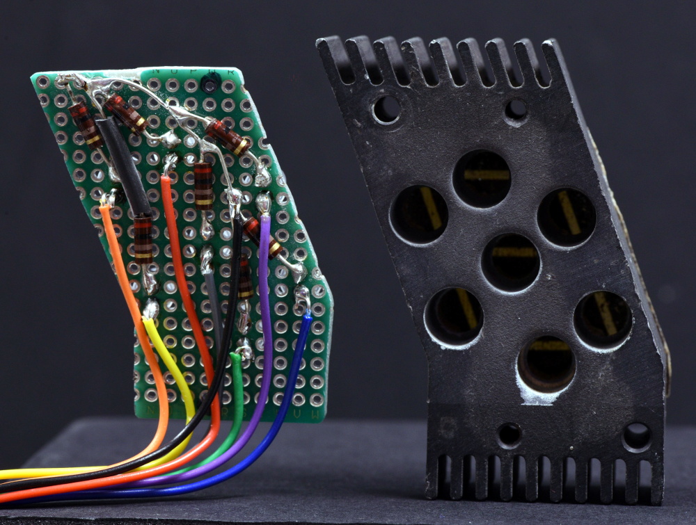
Currently, [Patrick] is putting most of his efforts on the smaller of the two displays that he calls “Type A”. The chunk of milled aluminum with integrated cooling fins has a relatively simple shape that should lend itself to replication through 3D scanning or even just a pair of calipers. He’s also put together a proof of concept for how he intends to light the display with 5mm LEDs on a carefully trimmed bit of protoboard, which he plans on eventually refining to reduce the number of wires used.
One aspect he’s still a little unsure of is how best to replicate the front mask. It appears to be made of etched metal with an integrated fiberglass diffuser, and while he’s already come up with a few possible ways to create a similar front panel for his 3D printed version, he’s certainly open to suggestions from the community.
This isn’t the first time we’ve seen a dedicated individual use 3D printing to recreate a rare and expensive object. While the purists will say that an extruded plastic version doesn’t compare to the real thing, we think it’s certainly better than letting technology like this fade into obscurity.