A bench oscilloscope is one of the most invaluable tools in the hardware hacker’s arsenal, but even the slimmest digital models are a bit large to be part of your everyday electronic carry. Sure you could throw one of those cheap pocket scopes in your bag, but what if there was an even easier way to take a peek at a few signals while you’re on the go?
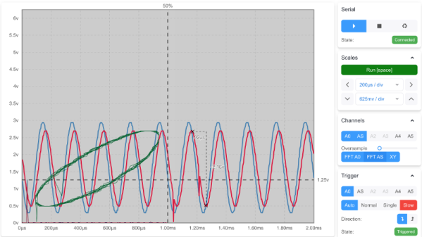
For those who roam, the Arduino-web-oscilloscope project created by [David Buezas] is worth a close look. Using the Web Serial API built into recent versions of Google’s Chrome browser, this project allows you to pop open a software oscilloscope without installing anything locally. Whether it’s a public computer or that cheap Chromebook you keep around for emergencies, a valuable tool is just a few clicks away.
Of course, there has to be some hardware involved. Despite what you might think given the name of the project, the code currently only supports the Logic Green LGT8F328P microcontroller. This cheap ATmega328P clone not only runs at 32 Mhz but according to [David], many operations can be done in fewer clock cycles than on the original 328P. In short it’s fast, and fast is good if you want more samples.
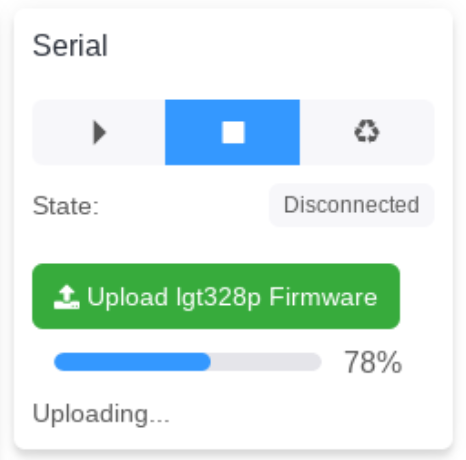
One of the best parts about this project is that a function to flash the firmware to the LGT8F328P is built right in the web interface. With the oscilloscope running in the browser, you just need to plug in a blank board, click the button to flash it, and start taking measurements. You could outfit a whole classroom or hackerspace with basic oscilloscopes in minutes, with a per-seat cost of just a few bucks.
Now as you might expect, there are some pretty hard limits on what you can realistically measure with this setup. For one thing, the board can’t handle anything higher than 5 volts. Even the cheapest oscilloscope kit is still going to be an upgrade, but the fact you can spin this up almost anywhere for the cost of a cheap MCU board makes it hard to complain about the results.
[Thanks to Bill for the tip.]