Dual Pet Food Dispenser Is Doubly Convenient

Does your dog or cat wake you up every morning, demanding to be fed? Maybe you feed Sparky in the evenings instead. But doesn’t that limit your spontaneity? It sure limited [Jorge]’s after-work plans. He has two dogs that eat the same type of food, but in different quantities. This was a big factor in the design and execution of his dual pet food dispenser.

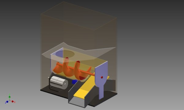
[Jorge] started by modeling his requirements in 3D. Dispensing takes place in two stages as food moves from the storage hopper to the bowls. A 12V printer motor turns the 3D-printed auger, which transports the nuggets to the staging area. Here, a servo controls a ramp in a see-saw motion, sending the food sliding sideways into one bowl or the other.

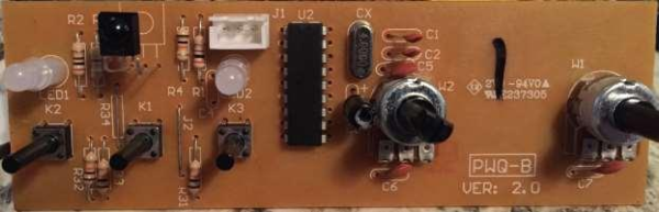
The dispenser is designed around a PIC18F2420. Although this micro was [Jorge] ‘s second choice, it ticks all the boxes in the design. His acrylic enclosure features four push buttons for navigation and selection through the 16×2 LCD. [Jorge] has an issue with the food getting stuck in the first stage. A friend suggested that he use vibration to agitate the food, but that didn’t work. [Jorge] ultimately added a stirring shaft with spokes that helps keep the morsels moving. Take the tour after the break.

If you want to dispense single doses of food on a timer, check out this automatic cat feeder made from scavenged parts.

Continue reading “Dual Pet Food Dispenser Is Doubly Convenient”

More GPIOs For The ESP8266

The ESP8266 is an incredible piece of hardware; it’s a WiFi module controllable over a serial port, it’s five freaking dollars, and if that’s not enough, there’s a microcontroller on board. Until there’s a new radio standard, this is the Internet Of Things module.

The most common version of the ESP, the -01 version, only has a 2×4 row of pins for serial, power, configuration, and two lines of GPIO. It’s a shame that module only has two GPIOs, but if you’re good enough with a soldering iron you can get a few more. It took a lot of careful soldering, but [Hugatry] managed to break out two more GPIOs on this tiny module.

According to [Hugatry] a lot of patience to solder those wires onto those tiny pads, but after finishing this little proof of concept he discovered a Russian hacker managed to tap into four extra GPIOs on the ESP8266-01 module (Google Translatrix).

As a proof of concept, it’s great, but there’s more than one ESP module out there. If you’re looking for a cheap WiFi module, check out the ESP-03, -04, or -07; they have nice castellated pins that are exceptionally easy to solder to.

Video below.
Continue reading “More GPIOs For The ESP8266”

LED Matrix Plus Geiger Counter

A lot of projects get made because someone just has the parts lying around. In this case, [Ed Nisley] got given a nice 8×8 RGB LED matrix, and needed something to display. [Ed] details the transformation of stuff-lying-on-the-desk into a unique matrix display for a Geiger counter (which he also presumably had sitting around somewhere). The result is a lightshow that’s as random as radioactive decay, and that’s pretty darn random.

img_5583-random-led-dots-circuit-layout-rb-smd-resistorsThe first post covers the hardware layout. It’s build on protoboard, but ends up looking a lot nicer than our projects because [Ed] spent some time hiding the shift-register ICs and row-driver transistors underneath the matrix itself, which was nicely socketed above. A sweet touch is the use of SMT resistors soldered upright underneath the board to save space. Cute.

The second post covers the circuit design, and is worth a look if you’re new to driving many LEDs from a minimum number of microcontroller pins. There are eight rows, and three colors each for eight LEDs per row. Without using shift registers, this would require 8*8*8*8 = way too many pins to control. If you want a worked example of how to do this with just four microcontroller pins, have a look. (Spoiler: cascaded shift registers driven by the AVR’s hardware SPI peripheral.)

The third post starts to flesh out the software. [Ed] settled on seven colors (and off) for the display, so the matrix’s total state can be crammed into just 32 bytes, which fits nicely in even a tiny microcontroller, much less the gargantuan ATmega328. Wrapping this all up in an array of structs and providing a couple of helper functions makes quick work of the software side. The addition of a sync pulse to trigger an oscilloscope at the end of a row is a nice touch.

aware-rm-60-geiger-pulseNext up is the Geiger counter interface software post. When a radioactive decay event is detected, the code reads out the time in milliseconds and uses that as the source of randomness. To whiten the noise, the times are run through a simple hash function: the Jenkins hash (link). This hash function was new to us and seems pretty useful for quick-and-dirty microcontroller applications.

The last post details pre-loading the matrix on startup and running a test sequence that blinks each LED to make sure they’re all working. Using a single random value to seed a software pseudo-random number generator ensures that it will (almost) never start off with the same display twice.

Phswew! That’s a lot of well-documented writeup of a well-polished project! Hope it inspires you to dig out something cool from your junk drawer and build.

Tessel 2, A $35 Linux Computer That’s Truly Open Source

We’ve seen the first version of the Tessel a few years ago, and it’s still an interesting board: an ARM Cortex-M3 running at 180MHz, WiFi, 32 Megs of both Flash and RAM, and something that can be programmed entirely in JavaScript or Node.js. Since then, the company behind Tessel, Technical Machines, has started work on the Tessel 2, a board that’s continuing in the long tradition of taking chips from WiFi routers and making a dev board out of them. The Tessel 2 features a MediaTek MT7620 running Linux built on OpenWRT, Ethernet, 802.11bgn WiFi, an Atmel SAMD21 serving as a real-time I/O coprocessor, two USB ports, and everything can still be controlled through JavaScript, Node, with support for Rust and other languages in the works.

Instead of going the usual route and determining the future of Tessel through market research and the apparent pragmatism of whoever happens to be in charge, this week Technical Machines did something wonderful: the ownership and direction of the Tessel Project is now independent of Technical Machine. This makes Tessel a completely open source and community driven platform for I0T, robots, and whatever else would benefit from an open source community disconnected from hardware.

The Tessel project is completely disconnected from manufacturers, something the Arduino project has been struggling with for the last few years, unbeknownst to most of the founders for most of that time. It’s a boon for the open source community, and something that should see an incredible uptake in the next few months.

Unix On Your Breadboard

As smartphones continue to get bigger and bigger, the race to have the smallest chip running Unix (or Linux, as the case may be) is still on. A new contender in this arena is [Serge] who has crammed RetroBSD on a Fubarino microcontroller for a powerful breadboard-friendly device.

The device uses a PIC32MX795 processor to run version 2.11BSD Unix for microcontrollers. It uses only 128 kbytes of RAM which is great for the limited space available, but it doesn’t skimp on software. It has a C compiler, assembler, and a whole host of other utilities that you’d expect to find in something much more powerful. All of this comes in a package that has breadboard-compatible pins so you can interface your Unix with the real world.

There’s a video below that shows the device in action, and a whole host of instructions that’ll get you up and running in no time if you have the hardware available. [Serge] mentioned that this would run on other architectures but is looking for others to join the project to port it to those processors. This isn’t the first time we’ve seen *nix installed on a microcontroller, but it is one of the more useful ones!

Continue reading “Unix On Your Breadboard”

Fixing A Product Design Flaw In A Misting System

[Xerxes3rd] works at a place where they raise reptiles in terrariums. Such enclosures require controlled lighting, temperature and humidity. Humidity is maintained using “misting” devices. These are usually water containers with a pump whose outlet ends in a series of very fine spray nozzles which create the mist. A timer controls the pump’s on and off cycles.

[Xerxes3rd] purchased an Exo Terra Monsoon RS400 misting system – a low-cost misting device and soon discovered that it had a serious design flaw. The built-in timer malfunctions, and it mists a hundred times more than it should! A lot of folks who buy a product and discover it has an inherent design flaw will return it back for a refund. Instead,  [Xerxes3rd] decided to break in and fix it instead –  “warranty void if tampered” be damned.

To start with, he needed to figure out what the problem was. He went about it in clinical fashion, eventually creating a slick document (PDF) outlining his observations and diagnosis. The timer controller board has a PIC micro, some buttons, potentiometers, LED’s and an IR receiver. The misting cycles are set using the two potentiometers – Off time and On time for the pump. His analysis and resolution makes for interesting reading.

What he found was that the PIC micro was reading inconsistent values from the potentiometers. More specifically, the software isn’t doing any smoothing on the analog values it reads from the potentiometers. Since the PIC that controls the system wasn’t easily re-programmable, he opted to replace it with an Arduino Nano. At the same time, he got rid of the potentiometers that were used to set the misting frequency and duration, and added a 16×2 LCD. Time setting is now done using the three on board buttons. He removed the PIC micro and replaced it with two female header sockets, onto which he plugged a small board containing an Arduino Nano and a few components. He also cut the original PCB in half, removing the potentiometers and crystal oscillator in order to make room for the 16×2 character LCD.

The lizards are now probably thanking him for their perfectly timed doses of moisture. Having done this, he could probably add in more features such as a temperature-humidity sensor, a water level sensor or maybe even throw in an ESP8266 module and have the Lizards tweet when they need to be hydrated. Because that’s another thing hackers love – feature creep.

An Amazon Dash-Like Button For The ESP8266

The Amazon Dash Button is a tiny piece of hardware that contains a single pushbutton, a WiFi module, and a nice, shiny corporate logo. Press the button, and products with that logo will be delivered to your house. An impressive bit of marketing, at least. With small, cheap WiFi modules like the ESP8266, it was only a matter of time until something an Amazon Dash clone was developed.

[deqing] created an ESP8266 Dash Button using the ESP-12 module, a button, a 3D printed case, and a pair of AA batteries. Electronically, it’s extremely simple; press the button, the ESP will wake up, request a URL, and put itself back to sleep. That’s all you need to do when you’re replicating the functionality of the Amazon Dash Button – the server will take care of the rest.

To configure the ESP8266, [dequng] is using the ESP-TOUCH app for Android, and setting up new functionality in this ESP button is as simple as putting a URL in the button’s Flash.

Not only is this a great build that has literally hundreds of different uses, it’s also not a breakout board for the ESP8266. It’s great that we’re finally seeing some builds using this cheap WiFi chip in the real world.

Obviously the actual Dash buttons include authentication that this one does not. We recently saw a teardown of the original hardware. We’re still waiting for in-depth analysis of the data squirted to the internet when an order is placed with it, though.