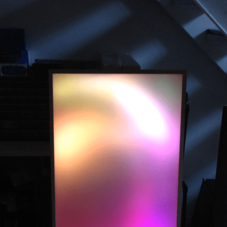
[Mark] recently finished his latest project, where he encrypts wireless communications between the new Intel Galileo and a Texas Instruments MSP430. The wireless interfaces used are the very common nRF24L01+ 2.4GHz transceivers, that had a direct line of sight 15 feet range during [Mark]’s tests. In his demonstration, the MSP430 sends an encrypted block of data representing the state of six of its pins configured as inputs. This message is then received by a sketch running on the Galileo and stored in shared memory. A python script then wakes up and is in charge of decrypting the message. The encryption is done using AES-128bits in Electronic Codebook mode (ECB) and semaphores are used to prevent simultaneous accesses to the received data. As it is the first project using an Intel Galileo we received, don’t hesitate to send us a tip if you found other ones.
Microcontrollers2215 Articles
A Killer Arcade Cabinet For Halloween
It’s already pretty cool that [Clay] co-owns an Arcade, but he’s really impressed us with his custom-made Splatterhouse cabinet built to get his patrons in the Halloween spirit! A Namco brawler title from 1988, Splatterhouse came in an unadorned and otherwise forgettable cabinet. [Clay] salvaged an old Williams Defender, coating the sides with a cocktail of drywall compound, sand, and paint to achieve a stone texture. He then carved up some pink insulation foam into a tattered “wooden” frame and used it as a monitor bezel. For accents, he fashioned strips of latex to resemble torn flesh and placed them among the boards. The control panel is yet another work of art: [Clay] 3D printed a life-size human femur for the game’s joystick, and converted the buttons to look like eyeballs.
[Clay] decided to go beyond the stunning cosmetics, though, and tapped into the game’s CPU with a custom daughterboard that detects different in-game events and state changes such as player health. An ATMega165 uses four PWM outputs connected to a number of LEDs inside the cabinet and around the monitor bezel to react to the different events. If a player takes damage, red lights flash around the monitor. Inserting a coin or dying in the game causes a different set of LEDs behind the marquee to go nuts.
Check out his detailed project page for more information and see a video overview below. If building a full-scale arcade machine is out of your budget, you can always make a tiny one.
Serial USB For Any AVR Microcontroller
If you’re using an AVR microcontroller and you’d like to add USB to a project, there are a lot of options out there for you. Both LUFA and V-USB add some USB functionality to just about every AVR micro, but if you’d like a native serial port, your only options are to look towards the USB-compatible Atmel micros.
[Ray] looked at the options for adding a USB serial port and didn’t like what he saw; seemingly, this was an impossible task without a second, more capable microcontroller. Then he had an idea: if the goal is only to transfer data back and forth between a computer and a microcontroller, why not write an HID-class USB serial port?
[Ray] based his project on The V-USB library and created a new HID descriptor to transfer data between a micro and a computer. While it won’t work with a proper terminal such as Putty, [Ray] managed to whip up a serial monitor program in Processing that’s compatible with Windows, Linux and OS X.
In the video below, you can see [Ray] using an ATmega328p with a standard V-USB setup. He’s transferring analog values from a photoresistor as a proof of concept, but just about everything that would work with a normal serial port will work with [Ray]’s library.
Turn A PC On With A Knock And An ATTiny
Pressing the power button on your computer usually isn’t too much trouble, unless your computer is stored away somewhere hard to reach. [Joonas] has been hard at work on a solution that would also impress his friends, building a knock sensor to turn on his PC.
For around $10 in parts he put together an ATTiny45 that emulates a PS/2 device, which takes advantage of his computer’s ability to boot upon receiving PS/2 input. The build uses a Piezo buzzer and a 1M Ohm resistor as a knock sensor exactly as the official Arduino tutorial demonstrates, and one of those PS/2-to-USB adapters that are most likely lurking in the back corner of every drawer in your office.
[Joonas] used AVRweb to disable the 8X clock divider so there’d be enough clock cycles for PS/2 communication, then loaded some test code to make sure the vibrations were being detected correctly. You can check out his Github for the final code here, and stick around after the break for a quick video demo. Then check out a similar hack with [Mathieu’s] home automation knock sensor.
The Most Minimal Homebrew Computer
Perfection is achieved not when there is nothing more to add, but when there is nothing left to fail. Going by that metric, [Stian]’s three-chip 6502 homebrew computer is the epitome of perfection. It’s a real, working, homebrew retrocomputer using only three chips: a CPU, some RAM, and a microcontroller to bootstrap the computer and provide a video output,
The key to this minimalist build is having the entire boot process controlled by an ATMega16 microcontroller, This interfaces to the 6502 through a dual-port SRAM, a 1 kilobyte Cypress CY7C130. This dual-port RAM allows the CPU and microcontroller to access the same bit of memory, making it easy to bootstrap a computer from a bit of AVR code.
Output is provided with [Stian]’s ATMega video text generator putting a 37×17 characters on any television with an RCA jack. While input isn’t handled yet, [Stian] says it should be possible with his AVR PS/2 keyboard library.
While other 6502 homebrew computers such as [Quinn Dunki] Veronica can reach unparalleled heights of complexity, there is a lot to be said about the minimalism of [Stian]’s three-chip computer. With some clever coding and a modified parts list, it may well be possible to put a retrocomputer in the hands of everyone with a bare minimum of cost and parts.
Build A Sensorless Brushless DC Motor Controller
[Davide Gironi] shows us how to implement a sensorless brushless DC motor controller (sensorless BLDC) using an ATmega8 microcontroller. In order to control a BLDC motor you need to know its rotational sequence position and speed so you can calculate and apply the correct current phase sequence to the motor windings at just the right time.
Simply said, sensorless BLDC means you’re not using a purpose built sensor to determine the motor’s position and speed, however, you are sensing the motor’s sequence position using the back EMF signal coming from one of motor’s coils that is not currently receiving power. When this back EMF signal crosses zero voltage a microcontroller can calculate the rotational speed and when to switch to the next power sequence. This technique is not good for position control motors but is great for continuous motors like computer fans and drives were the slightly reduced wiring costs make this type of BLDC control favored.
If you want to build a BLDC controller we recommend starting with [Davide’s] last project on sensor controlled BLDC motors. You can also checkout these interactive demonstrations for more understanding on the different BLDC configurations.
Follow along after the break to watch the video demonstration of [Davide’s] sensorless BLDC controller controlling a motor from CD-ROM drive.
Continue reading “Build A Sensorless Brushless DC Motor Controller”
Making A Diode Matrix ROM
Here is a nice project that allows youngsters (but also adults!) to actually see the data stored in a Read Only Memory (ROM). The memory shown in the picture above is made of diodes. [Scott] made it as a part of his Barcamp Fall 2013 presentation about visualizing ROMs. He starts his write-up by stating the obvious: this memory is not practical. Nonetheless, it still was a fun exercise to do. [Scott] then greatly described all the different kinds of read only memories that you can find out there, with a few words explaining how they work. In his diode ROM, bits are ‘programmed’ by adding (or not) a diode between a given data line (anode) and an address line (cathode). When pulling low a given address line, the corresponding data line will only be pulled low if a diode is present. [Scott] finally checked his circuit by using a very old device programmer which could only be run in DOS.