The Mystery Of Zombie RAM

[Josh] had a little project where he needed to keep a variable in RAM while a microcontroller was disconnected from a power source. Yes, the EEPROM on board would be able to store a variable without power, but that means writing to the EEPROM a lot, killing the lifetime of the chip. He found an ATTiny can keep the RAM alive for a variable amount of time – somewhere between 150ms and 10 minutes. Wanting to understand this variability, he decided to solve the mystery of the zombie RAM.

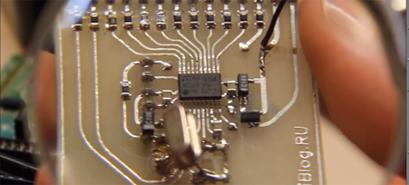
The first experiment involved writing a little bit of code for an ATTiny4313 that looked for a value in RAM on power up and light up a LED if it saw the right value. The test circuit consisted of a simple switch connected to the power pin. Initial tests were astonishing; the ATTiny could hold a value in RAM for up to 10 minutes without power.

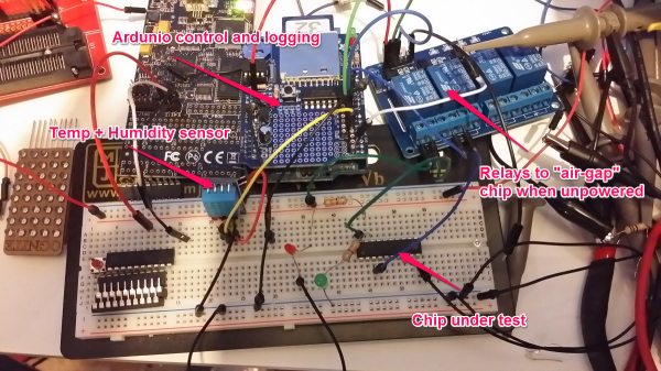
With the experiment a success, [Josh] updated his project to use this new EEPROM-saving technique. Only this time, it didn’t work. The value hidden away in RAM would die in a matter of milliseconds, not minutes. After tearing his hair out looking for something different, [Josh] rigged up an Arduino based test circuit with humidity and temperature sensors to see if that had any effect. It didn’t, and the zombie RAM was still not-undead.

The key insight into how the RAM in an ATtiny could stay alive for so long came when [Josh] noticed his test circuit had a LED, but the actual project didn’t. Apparently this LED was functioning as a very tiny solar cell, generating a tiny bit of current that kept the RAM alive. A dark room with a flashlight confirmed this hypothesis, and once [Josh] gets his uCurrent from Kickstarter he’ll know exactly how much current this LED is supplying.

TI Launches “Connected LaunchPad”

TI’s LaunchPad boards have a history of being both low cost and fully featured. There’s a board for each of TI’s major processor lines, and all of them support the same “BoosterPack” interface for additional functionality. Today, TI has announced a new LaunchPad based on their new Tiva C ARM processors, which is designed for connectivity.

The Tiva C Series Connected LaunchPad is based on the TM4C129x processor family. These provide an ethernet MAC and PHY on chip, so the only external parts required are magnetics and a jack. This makes the Connected LaunchPad an easy way to hop onto ethernet and build designs that require internet connections.

This development board is focused on the “Internet of Things,” which it seems like every silicon manufacturer is focusing on nowadays. However, the real news here is a low cost board with tons of connectivity, including ethernet, two CANs, 8 UARTs, 10 I2Cs, and 4 QSPIs. This is enough IO to allow for two BoosterPack connectors that are fully independent.

Connected Launchpad Details

For the launch, TI has partnered with Exosite to provide easy access to the LaunchPad from the internet. A pre-loaded demo application will allow you to toggle LEDs, read button states, and measure temperature over the internet using Exosite. Unlike some past LaunchPads, this one is designed for easy breadboarding, with all MCU pins broken out to a breadboard compatible header.

Finally, the price is very right. The board will be release at $19.99 USD. This is less than half the price of other ethernet-ready development boards out there. This makes it an attractive solution for hackers who want to put a device on a wired network, or need a gateway between various devices and a network. 

Bench Power Supply Constant Current EZ-SET

constant_current_mod3

Here is a nice hack you may find very useful if you have a cheaper bench power supply that supports constant current limit protection (CC mode) and the only way to set or check your max current limit is to disconnect your circuit, short the power supply outputs and then check or set your limit. Yes, what a pain! [Ian Johnson] was enduring this pain with a couple of Circuit Specialist bench power supplies and decided to do something about it. After finding a download of the circuit diagram for his CSI3003X-5 supply he was able to reverse engineer a hack that lets you press a new button and dial-in the max current setting. Your first guess is that he simply added a momentary button to short the power supply outputs, but you would be wrong. [Ian’s] solution does not require you to remove the load, plus the load can continue running while you set your current limit. He does this by switching the current display readout from using 0–3 volts off an output shunt resistor to using the 0-3 volts output from a digital potentiometer which is normally used to set the power supplies’ constant current limit anyway. So simple it’s baffling why the designers didn’t include this feature.

Granted this is a simple modification anybody can implement, however [Ian] still wasn’t happy. A comment by [Gerry Sweeney] set him on the path to eliminate the tedious multi-button pressing by implementing a 555 momentary signal to switch the circuit from current load readout to current set readout. This 2nd mod means you just start pressing your up-down CC set buttons and it momentarily switches over the display to read your chosen max current and a few moments later the display switches back to reading actual load current. Brilliant! Just like the expensive big boy toys.

[Ian] doesn’t stop with a simple one-off hack job either. He designed up a proper PCB with cabling and connectors, making an easy to install kit that’s almost a plug-in conversion kit for Circuit Specialist bench power supplies (CSI3003X-5, CSI3005X5, CSI3003X3, CSI3005XIII). It is not a 100% plug-in kit because you do have to solder 3 wires to existing circuit points for signal and ground, but the video covering that task seemed trivial.

This hack could very well work with many other power supplies on the market being Circuit Specialist is just rebadging these units. For now, only the models listed after the break are known to work with this hack. If you find others please list in the comments.

After the break we will link to all three progressive mod videos incase you want to learn how to mod your own power supply or you could just order a prebuilt kit from [Ian].

Continue reading “Bench Power Supply Constant Current EZ-SET”

Interrupt Free V-USB

resync

[Tim’s] new version of Micronucleus, Micronucleus 2.0, improves upon V-USB by removing the need for interrupts. The original Micronucleus was a very small implementation of V-USB that took up only 2KB. Removing the need for interrupts is a big leap forward for V-USB.

For those of you that do not know, “V-USB is a software-only implementation of a low-speed USB device for Atmel’s AVR® microcontrollers, making it possible to build USB hardware with almost any AVR® microcontroller, not requiring any additional chip.” One tricky aspect of using V-USB is that the bootloader requires interrupts, which can lead to messy problems within the user program. By removing the need for interrupts, Micronucleus 2.0 reduces the complexity of the bootloader by removing the need to patch the interrupt vector for the user program.

With the added benefit of  speeding up the V-USB data transmission, Micronucleus 2.0 is very exciting for those minimal embedded platforms based on V-USB. Go ahead and try out Micronucleus 2.0! Leave a comment and let us know what you think.

Public Transportation Display

display_cropped

[Adrian] and [Obelix] wanted to have an easy way to know when to expect the public transportation, so they hacked an LED dot matrix display to show arrival times for stops near their dorm.

They found the display on Ebay with a defective controller which they replaced with an ATmega328p. They connected the display to the internet by adding a small TP-Link MR3020 router and connecting it to the ATmega328p via a serial line. Their local transportation office’s web page is polled to gather wait times for the stops of interest. All rendering of the final image to display to the dot matrix display is done on their PC, which then gets pushed through to the MR3020, which in turn pushes it out to the ATmega328p for final display.

[Adrian] and [Obelix] warn about setting proper watchdog timers on the display driver to make sure bugs in the controller don’t fry the dot matrix elements. Their ATmega328p dot matrix driver code can be found on [Adrian]’s GitHub page.

Check out a video of the display in action after the jump.

Continue reading “Public Transportation Display”

Software USB On The STM8

STM8

Thanks to V-USB, software-based USB is all the rage now, with a lot of uses for very small and low power microcontrollers.[ZiB] wondered if it would be possible to implement a USB controller on the STM8 microcontroller (Google translation) in software and succeeded.

The STM8 is a bit of a change from the usual 8-bit micros we see like AVRs and PICs. [ZiB] chose the STM8S103F3, although any chip in the STM8 family will work with this project when a 12MHz crystal is attached.

The build began by generating USB signals with the help of a whole lot of NOPs. This code doesn’t take up much space – only 300 bytes, and the receiving code (Google translation) is similarly sized.

The code isn’t quite there yet, but [ZiB] has proven a software-based USB implementation on the STM8 is possible. All the code is available for download (comments in Russian) and a video demoing the project available below. If anyone cares to translate this project to English, we’ll post a link to your work here.

Continue reading “Software USB On The STM8”

Microcontroller Speech Synthesis Lets Your Project Be Heard

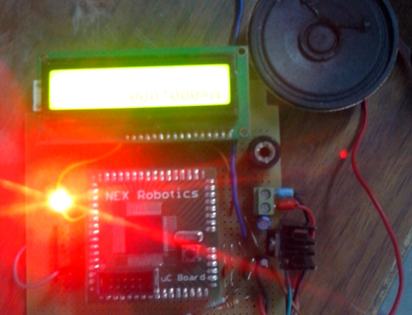
[Aditya] had a project that called for spoken output. He admits that he could have built a PC-based solution, but he found that adding speech by using a microcontroller was not only a cheap and portable alternative, it was also a fun and easy build.

His design uses an ATMega128. Many microcontrollers would work, but his major requirements were PWM generation and plenty of memory to store the file(s). The output is cleaned up in a simple low pass filter before going to the 8Ω speaker.

[Aditya] lays his tracks in WAV format and then compresses it to 8-bit/8kHz. He found a C++ function that converts the track data into a huge arrays and then digitizes it. He uses two timers, one to generate the waveform and second one to time the square wave. [Aditya] has a zip of samples available on his site that will speak the digits 0-9.