Passive RFID Tag Cloning

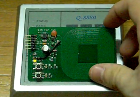
Here’s an open source RFID cloner design that is about the same size as a standard RFID key card. It doesn’t need a battery to capture key codes, just the magnetic field generated by an RFID reader. You can see the functionality demonstrated in the video after the break. By holding the bottom button as the cloner is moved in range of the RFID reader, the microcontroller goes into learning mode. Now just hold up the card you wish to clone and the LED just above the buttons will light up when it has captured the code. Now the device will act just as the original RFID tag did.

This was developed by [Ramiro], the same person who built the barebones RFID emulator we saw a few days ago. When researching that story we complete skipped over this gem. He’s posted a ton of information on the tag itself. It doesn’t look like he has any PCBs or kits left, but the schematic and code are available for download. You should check in on the design considerations section because it discusses the read/write function that isn’t built into the current version. That’s why you see some add-on components on the hardware used in the demo video.

It seems like this is a lot more user-friendly than the last RFID spoofer we looked at.

Continue reading “Passive RFID Tag Cloning”

Basic Micro ATOM Nano Giveaway

basic_micro_atom_nano_giveaway

UPDATE:
As several readers have already noted, these things sold out very quickly – in less than 15 minutes!  Big thanks to Basic Micro!

If you have been considering the purchase of a Basic ATOM Nano product, but you weren’t quite ready to lay down the cash for a dev board and Nano microcontroller, boy to we have a deal for you. The kind folks at Basic Micro informed us that they have 55 Basic ATOM Nano Development boards, complete with Nano 28 microcontrollers that they would like to give away to the Hack a Day community for the low, low cost of $0.

That’s right. Zero. Zip. Zilch.

The dev boards come complete with an LCD header, a small solderless breadboard, USB connectivity, a pair of servo connectors, and more! The Nano 28 is based on the PIC16F886 microcontroller, and features an 8MHz clock,  24 I/O pins, 14K of flash memory, 368 bytes of memory, and 256 bytes of EEPROM storage.

The total value of the package is just around $50, so this is an incredible deal! Basic Micro will even ship your kit to you for free via USPS.

Just add this item to your shopping cart on the Basic Micro site, and use the coupon code “freehack” at checkout – they’ll take care of the rest.

There are a few caveats to this giveaway, and they are as follows:

1) To participate, you must reside within the contiguous United States – i.e. anywhere in the lower 48 (Sorry readers from Alaska or Hawaii!)

2) The offer is limited to one kit per individual. Let’s not be greedy here, give your fellow hackers a chance at this deal as well.

3) Once these dev boards are sold out, they are gone for good. There are no rain checks or back orders available.

4) You must build something cool with your kit and share it with us in our forums or via the tip line*

*Not really, but it would be pretty cool if you did.

[Thanks to Dale at Basic Micro for putting this together for us!]

MSP430-based Wristwatch Project

[Nav] is working on a scratch-built wristwatch. Although it is based on an MSP430 microcontroller, it’s not the ready-to-hack ezCronos that you might be thinking of. Instead, [Nav] started with a different TI development tool that we’ve looked at before, the ez430-F2013.

The breakout board for the F2013 is small enough to meet his needs, but still provides easy soldering with 0.1″ vias that break out each pin. To make sure the timepiece is accurate he added a 32.768 kHz clock crystal. A small, square, LCD screen acts as the face of the watch, but we didn’t find specific part information for the display.

Currently the watch can run for a few days on the CR2032. We’d bet some work with sleep modes for the microcontroller can help with that. The watch has a couple of buttons that let you control it, and [Nav] discovered that he could fit everything into the watch case for an iPod nano. That’s creative!

We’ve seen other hacks with tiny batteries. The next logical step here would be to swap out the disposable coin cell for something that can be topped off with an external charger.

Running The Linux Kernel On A DE0-nano FPGA Board

[Mike] has been filling up a rather intense wiki entry outlining how to run uClinux on a DE0-nano FPGA board. This is an inexpensive dev board that will run you somewhere between $80 and $100. Right off the bat he goes into a hefty list of the reasons that this is a foolish activity. To name a few: Once you’ve complete the build the device will be tethered for reboot.  This board doesn’t have Ethernet hardware and TCP/IP is one of the beast features of the uClinux kernel. And the FPGA tools are closed-source, which doesn’t often mesh with the ideals of Linux developers. But we still like to see what it really takes to get these large-scope firmware builds to compile and load correctly.

After his preamble you’ll find three main chunks. The first deals with setting up the toolchain on Fedora 14. From there, he installs packages necessary for cross-compiling, pulls down the source packages, and gets to work. Once the kernel is compiled and running on the FPGA [Mike] goes on to show you how to build out a simple hardware add-on in the form of a couple of LEDs connected to extra FPGA pins. The final portion of the wiki details rolling support for toggling the LEDs into the software distribution.

Two Dice, One 8-pin UC

[Mike Shegedin] makes full use of an 8-pin microcontroller with this ATtiny13-based dice project. With a maximum of six I/O pins (that includes using the reset pin as I/O) he needed a couple of tricks in order to drive 14 LEDs and use a momentary push button for user input. We’re certainly familiar with the concepts here, but it still took quite a while to figure out what is going on with the schematic that [Mike] posted.

You’ve probably already guessed that he’s using Charlieplexing to drive more LEDs than he has pins. But when we started looking at the layout we thought he had drawn the schematic wrong, because there are six pairs of LEDs where the two diodes in each pair a not reverse biased, but hooked up in parallel. That, plus the fact that his battery is hooked up backwards. After several minutes of study the light bulb finally clicked on. Dice add pips (the dots on each side of a die) in pairs with the exception of the center pip. That means that you only need to control four total lines for each die (three pairs plus the center pip). There’s two ways to handle this, you could use four rows and two columns with traditional multiplexing, or you can reverse bias the two sets of LEDs for each die and use Charlieplexing. The former is a bit easier to program, the latter saves you one I/O pin and meant that [Mike] didn’t need to use the reset pin as I/O.

This is a clever addition to the collection of dice projects we’ve seen like the battery-less die, and the ATtiny2313 powered dice.

Building A Battery-powered Motion Alarm

[Brad] was asked by his Sister to design a motion-based alarm that would help her catch her son sneaking out of the house at night. Obviously this didn’t need to be a long-term installation so he decided to throw something together that is only active at night and can be battery-powered. What he came up with is a light-sensitive motion sensor that uses very little power.

He knew that an Arduino would be overkill, and decided to try his hand at using the Arduino to develop code for an ATtiny85. It has an external interrupt pin connected to the output of the PIR module, which triggers action when motion is detected. The first thing it does is to check the photoresistor via the ADC. If light levels are low enough, the buzzer will be sounded. [Brad] measured the current consumption of his circuit and was not happy to find it draws about 2.5 mA at idle. He spent some time teaching himself about the sleep functions of the AVR chips and was able reduce that to about 500-600 uA when in sleep mode. Now all he has to do is find a nice place behind the house to mount the alarm and there’ll be no more sneaking around at night.

If you’re trying to keep a tight leash on your own kids you could always make them punch the time clock.

Python On A Microcontroller

The team at LeafLabs was looking for something cool to do with their new ARM development board. [AJ] asked if anyone had ever played around with Python, so [Dave] cooked up an implementation of PyMite and put it on a Maple board. While the writeup is only about blinking a LED with a microcontroller, they’re doing it with Python, interactively, and at runtime.

The build uses the Maple Native board the team is developing. The board has a 32-bit ARM chip with 1 Meg of RAM – more than enough horsepower to run PyMite. The tutorial for putting PyMite on a Maple is up on the LeafLabs wiki.

PyMite is theoretically able to control every pin on the Maple Native and do just about everything a regular Python distro can do. The LeafLabs team is still working on the necessary libraries for their board (although we don’t see anything on the Google code page), so right now only blinking the LED is supported. Still, it’s pretty cool to have Python in your pocket.