Hack Improves Cheap Speed Controllers

[Tony Goacher] has worked with a lot of cheap brushless DC motor controllers built in China. They can be very cost-effective, but sometimes limited in performance or capability, particularly when it comes to low-speed operation. Thus, he’s been working on a project to make cheap controllers more capable.

The prime problems [Tony] has faced are jerkiness, throttle deadspots, and inconsistent torque delivery at low speeds. This is especially the case when running brushless motors on heavier vehicles, where the greater inertia can compound any minor problems to the point things become undriveable. [Tony]’s solution has been to create a signal interceptor that lives in between a throttle and the cheap motor controller to change their overall behavior.

The demo vehicle for this build is TrakTrike, a sort of bicycle-half-track hybrid that [Tony] built for EMF Camp 2022. After blowing up some nicer controllers, [Tony] specced some cheaper parts from AliExpress. Only, the low-speed control was terrible, and the dual motor controllers didn’t respond identically to throttle and would cause the vehicle to steer or crab, making driving difficult. This was fixed by dropping in an Arduino Nano after the throttle, and before the two motor controllers. It allows calibrating the throttle output from the Arduino to eliminate dead spots, while also tuning the throttle output to left and right motors individually so they respond more similarly. There are also custom acceleration and deceleration curves that make the controllers respond more smoothly, and a precise crawling speed for consistent low-speed maneuvering.

Just by doing some fancy throttle smoothing and control, [Tony] was able to greatly improve the usability of these cheap controllers, for the price of an Arduino Nano and little more. Files are on GitHub for those eager to attempt the hack themselves. There are other ways to go about this of course, like diving into field-oriented control, if you’re so inclined. Alternatively, speculate on how you’d tackle this engineering challenge down in the comments.

VFD Clock Runs On A Single AA

There are lots of different ways to build a clock. [Sciter_] came into the possession of some old calculator parts, and decided to reuse them for just such a project.

The heart of the build is an ATmega328P microcontroller, running off of a 32.768 kHz crystal. This allows the chip’s counters to neatly divide down the frequency to get a steady 1 Hz pulse for accurate timekeeping. Time is displayed on a vacuum fluorescent display (VFD) harvested from an old calculator. These displays need rather high voltages to run, which in this case are produced by a HV5812 driver chip and supporting circuitry. The display itself is neatly cradled in a pair of copper pipe elbows for a stylish look, with some addressable RGB LEDs present to provide some charming underglow.

Power for the device comes from a single AA battery, using a transformer-based low voltage converter. Alternatively, it can run off a USB 5 V power supply, which also charges the NiMH AA cell while available with the aid of an LM2576-ADJ buck converter.

Overall, it’s a neat homebrew clock that taught [Sciter_] plenty during its construction, and not the first time we’ve seen somebody put together a clock with second-hand VFDs. If you’re finding fun ways to reuse old display tech, don’t hesitate to let us know on the tipsline.

Building A Panel Mount OLED Display

There are a million and one cheap OLED display modules out there. The only problem is, they’re all assembled on bare PCBs with slight differences, and that frustrates efforts to mount them in a clean and tidy manner. [Galopago] decided to build a small OLED module that solved this frustrating problem.

The idea to pursue this came from off-the-shelf panel displays commonly used for power supply builds and other such equipment. These come in relatively standard sizes and are designed from the outset to slot neatly into a panel with a bezel that covers any ugly edges or awkward gaps.

The build began with a 48 x 29 mm enclosure grabbed from an off-the-shelf power panel meter. There are two PCBs—one holding the regulator and other equipment to run the display, the other carrying a set of screw terminals that make it easy to wire up the display to a piece of equipment. The SSD1306-compatible OLED screen itself connects to the first board with a flat flex cable, as is the norm.

If you find yourself often wanting to pop a small display into a piece of custom test equipment, this might be relevant to your interests. Files are on GitHub for the curious.

We’ve featured some other fun OLED hacks over the years, like this interesting effort to whip up displays from scratch in a home lab. If you’ve got nifty usability hacks of your own in the works, don’t hesitate to let us know.

Glue-in Hinge Design Tries Something Different

Need a hinge in your 3D printed design and would prefer not to re-invent the wheel? You may find [Alex Krush]’s glue-in filament hinge useful.

This design (shown in this simple box as an example) makes a very close-fitting hinge point.

This design prints half the hinge as a separate piece — the u-shaped one in the picture to the side — that must be glued into the target object after printing. It’s a bit of extra work, but doing it this way has a couple advantages.

One is that printing some of the hinge elements separately means one no longer needs to choose between a print orientation that best suits the object, and a print orientation that works best for the hinge. Also, the length of 1.75 mm filament used as a hinge pin is held captive after assembly so there’s no need to glue the hinge pin itself.

[Alex] helpfully provides the parts in STEP format, which makes CAD tweaks and adjustments easy. While incorporating the design should be doable even if one is just using .stl or .3mf files because boolean subtraction and merging is all that’s needed, having the model in STEP format is so much better.

Should you need some pointers on incorporating either into FreeCAD, we have you covered.

Texas Instruments Changes The NE5532 And Others Into Incompatible Versions

First introduced in 1979 by Signetics, the NE5532 was a pretty spiffy dual op-amp for the time with low noise and low distortion. Over the years it has become a standard part that showed up in countless audio products, and has become a so-called jellybean generic component with Texas Instruments (TI) being one of countless manufacturers.

It being such a standard, multi-sourced part makes it thus even more puzzling that TI has now decided to completely overhaul this IC in a way that makes it incompatible with even the original Signetics NE5532. These changes are covered in detail by [Dave] of EEVblog as his mind is pretty much blown at such an incomprehensible change.

The changes entail an entirely different manufacturing process and a big change in specifications, while making no change to the part number. In revision K of the TI datasheet these changes are first seen, with some specifications changed for the better, like a higher unity gain bandwidth by 2 MHz, but a much slower slew rate.

Kramer Electronics PT-102AN - board - Texas Instruments SA5532A
Texas Instruments SA5532A variant of the 5532 op-amp. (Credit: Raimond Spekking, Wikimedia)

Although the 5532 op-amps are multi-sourced, there are good reasons to just stick with manufacturers like TI, as that means receiving a product change notification (PCN) when anything changes. In the PCN related to this op-amp a change to process node is noted, along with other changes, but no reasoning.

Among the other big changes are a reduction in the supply voltage from 22 V to 18 V, and a halving of the ESD protection from 2 kV to 1 kV. Although it might be slightly more efficient on the new process node this way, it clearly comes with a lot of trade-offs that make it an overall worse op-amp, while also being incompatible with the same op-amp from other manufacturers.

In the video [Dave] goes through the datasheets of this jellybean part of other manufacturers, showing that they still have the original 1980s specifications. Only one exception here was the NE5532DR from Shenzhen HuaXuanYang Electronics, whose supply rail voltage is also 18 V for some reason, along with a similar internal transistor configuration that reduces the ESD resistance.

In addition to the NE5532 op-amp, it seems that TI also took an axe to the OPA134 op-amp, by removing its offset trim feature and listing the pins as ‘NC’, with a warning to not connect these pins and also worsening other specifications. This makes these similar jellybean parts incompatible, with no change to the part number. Worse is that it continues with the LMH6518, whose changes [Dave] argues might even kill oscilloscopes as they are commonly found in those.

Meanwhile the LM317M also got an overhaul, but here TI opted to give it a new part name, calling it the LM317MQ with at first glance no major degradations in the specifications, but instead some actual improvements. This makes it even more puzzling why TI didn’t give the other ICs a new part number to differentiate them from the jellybean part.

Until there’s some clarification from the side of TI, it might be a good idea to source these parts from a manufacturer that is not TI, especially when replacing these ICs in older devices.

Continue reading “Texas Instruments Changes The NE5532 And Others Into Incompatible Versions”

4-bit Relay Logic Counter Begs To Have Its Buttons Pushed

What’s one to do with some nice little relays of questionable pinout, and prototyping board? How about a quietly clicky 4-bit counter using relay logic with tons of buttons?

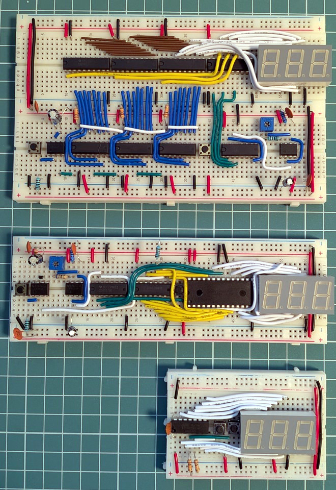
The register with LEDs and buttons is on the top board, the incrementer on the bottom board.

[Agatha Mallett] made the counter after finding herself in possession of a quantity of relays burdened by terrible documentation (the datasheet shockingly lacks a pinout, and doesn’t even mention the coil being unidirectional). But since the relays are also small and of decent quality, they were a good candidate for a small relay logic-based project.

The key to the build is implementing D-type flip-flops using relays. This is done by holding the coil voltage of each relay between its set and release voltage levels. A small voltage bump will energize the coil, closing the relay and leaving it closed. Conversely, a small negative spike releases the coil, leaving it open. This forms the basis of the counter, and [Agatha] has a separate write-up all about the details of using relays in this way.

Implementing this was rather less straightforward than it may sound because it relies on balancing the coils of many relays on a figurative knife-edge of voltage, but not every component is perfectly identical. A tweaked resistor or capacitor here and there was needed before things settled into reliability.

The end product has indicator LEDs, buttons to increment or clear the current count, and it even has buttons to set or clear individual bits. This is a project that begs to be interacted with, and there’s a short video on the project page so you can watch it go through its paces.

Thanks to [Jess] for the tip!

DIY Potentiometer Is A Great Teaching Aid

A potentiometer is a simple electrical device that allows resistance to be varied at will. Most everyone in the electronics field is intimately familiar with how they work on a fundamental level. Of course, we all had to be taught once, though, and a great way to do that would be with a teaching tool like the one [DiscoLapy] built.

What you’re looking at here is a very simple potentiometer that bares its function for all to see. It consists of a 3D printed base and knob, which form the mechanical part of the device. A paper track is then laid on top to act as the main resistive element, once properly covered with graphite from a regular old pencil. From there, it’s as simple as adding the necessary contacts and wiper to the device, and you’ve got a potentiometer sitting in front of you.

What’s great about this build is that it’s very intuitive. Just by looking at it or putting it together, you get a straightforward understanding of everything that’s going on. By drawing the resistive trace, and by turning the knob, particularly if hooked up to an LED or something like in the demonstration, it’s easy to see how the potentiometer varies its resistance and affects a circuit.

We’ve featured some other fantastic teaching tools in the past, too. If you’ve got your own educational gems, be sure to let us know.