How To Spot A Fake Op-Amp

We’re all aware that there are plenty of fake components to be found if you’re prepared to look in the right places, and that perhaps too-good-to-be-true chip offers on auction sites might turn out to have markings which rub off to reveal something completely different underneath. [IMSAI Guy] saw a batch of OP-07 laser-trimmed op-amps at a bargain price, so picked them up for an investigation. You can take a look at the video below the break.

A perfect op-amp has a zero volt output when both of its inputs are at the same voltage, but in practice no real device approaches this level of perfection. It’s referred to as the offset voltage, and for instrumentation work where a low offset voltage is important there are parts such as the OP-07 which have each been adjusted using a laser to trim their components for the lowest offset. This process is expensive, so naturally so are genuine OP-07s.

Identifying real versus fake op-amps in this case is as simple as hooking the chip up as a unity gain non-inverting amplifier and measuring the voltage on the output (we can’t help a tinge of envy at that Keithley 2015 THD multimeter!), from which measurement the fakes should be clearly visible. First up are some 741s with their > 1 mV offsets (though an outlier 741 had a 40μV offset) to show what a cheap op-amp could be expected to do, then we see the OP-07s. Immediately with an offset of > 1.2 mV  we can tell that they’re fake, which as he admits for the price is hardly a surprise. Meanwhile we’ll keep an eye out for Korean-made 741s like the outlier low-offset device.

If you’re interested by op-amp internals may we suggest a look at the first IC op-amp, meanwhile this isn’t the first fake chip we’ve seen.

Continue reading “How To Spot A Fake Op-Amp”

Planar PCB Coils As An Alternative To Winding Transformers

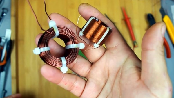
Those readers who have experimented with winding their own inductors will know that it’s not an easy task, and when those inductors are handling high voltages it can be especially tricky to maintain adequate insulation between layers of windings. [Open Frime TV] has a video addressing this in a novel way, by creating the windings for a switch-mode power supply transformer using stacked PCB coils instead of wire (Russian language; you’ll have to enable YouTube’s subtitle auto-translation).

The video below the break makes for a handy primer on PCB coil construction, reminding the viewer that the turns need all to lie in the same direction as well as the importance of insulation between windings. There’s a discussion of the properties of a PCB coil in relation to the switching frequency, and once the transformer has been assembled, we see it hooked up to a power supply board for a test. What happens next may be familiar to seasoned transformer-winders; nothing works, and the transformer gets hot. In making the PCB he’s left some copper on each board which amounts to a shorted turn — cutting these allows the transformer to work perfectly.

This technique might not be the solution to all transformer woes, but makes for an interesting option if your work takes you in the direction of winding transformers. If PCB coils take your interest, how about a Tesla coil using them?

Continue reading “Planar PCB Coils As An Alternative To Winding Transformers”

An MK-85 with a modern CPU replacement

Upgrading A Soviet Calculator With A Modern CPU

Today’s supply chain issues can make it hard to buy microcontrollers, or really any kind of semiconductor. But for those keeping retrocomputers alive, this problem has always existed: ancient components might have been out of production for decades, with a dwindling supply of second-hand parts or “new old stock” as the only option. If a rare CPU breaks, you might have no option but to replace the entire computer.

[Piotr Patek] ran into this issue when he obtained an Elektronika MK-85 programmable calculator with a broken CPU. Unable to find a replacement, he decided instead to build a pin-compatible CPU unit based on an STM32 microcontroller. Of course no modern CPU is pin-compatible with a Soviet design from the 1980s, so [Piotr] had to design a small interposer PCB to match the original pinout. This also gave him enough space to add an efficient DC/DC converter chip that generates the 2.5 V supply for the STM32.

As for the software, [Piotr] managed to port the original BASIC interpreter, which was written in PDP-11 assembly, to a modern equivalent written in C. While he was at it, he fixed a few bugs that had been sitting there for about 35 years. The updated CPU also allows the MK-85 to run circles around its contemporary siblings: [Piotr] timed it to be about thirty times faster than the original chip, while using a comparable amount of power.

If you also happen to have an MK-85 with a dodgy CPU, you’ll be pleased to find that the schematics and source code to [Piotr]’s modification are all available on his blog. This is probably the first calculator CPU update we’ve seen, although we’ve featured other ancient calculators updated with new firmware, and some completely new calculator designs based on classic hardware.

Thanks for the tip, [cmholm]!

555 Teardown Isn’t Just A Good Time, It’s To Die For

It seems only appropriate that hot on the heels of the conclusion of Hackaday’s 555 Timer Contest that [Ken Shirriff] posts a silicon die teardown of an early version of a hacker’s favorite chip, the 555.

A Microscopic View Of the 555 Die

Starting with a mystery chip from January 1973, [Eric Schlaepfer] painstakingly sanded down the package to reveal the die, which he deemed to be a 555 timer. Why didn’t they know it was a 555 timer to start? Because the package was not marked with “555” but rather some other marks that you can see in the blog post.

In addition to a great explanation of how the 555 works in general, [Ken] has taken a microscopic look at the 555 die itself. The schematic of a 555 is easily available, and [Ken] identifies not just sections of the die but individual components. He goes further yet by explaining how the PNP and NPN resistors are constructed in silicon. There’s also a nice and juicy bit of insight into the resistors in the IC, but we won’t spoil it here.

Be sure to show your love for the winners of the 555 contest, or at the very least check out the project that took the stop spot: a giant sized 555 that you don’t need a microscope to see inside of.

Remoticon 2021 // Debra Ansell Connects PCB In Ways You Didn’t Expect

“LEDs improve everything.” Words to live by. Most everything that Debra Ansell of [GeekMomProjects] makes is bright, bold, and blinky. But if you’re looking for a simple string of WS2812s, you’re barking up the wrong tree. In the last few years, Debra has been making larger and more complicated assemblies, and that has meant diving into the mechanical design of modular PCBs. In the process Debra has come up with some great techniques that you’ll be able to use in your own builds, which she shared with us in a presentation during the 2021 Hackaday Remoticon.

She starts off with a quick overview of the state of play in PCB art, specifically of the style that she’s into these days: three dimensional constructions where the physical PCB itself is a sculptural element of the project. She’s crossing that with the popular triangle-style wall hanging sculpture, and her own fascination with “inner glow” — side-illuminated acrylic diffusers. Then she starts taking us down the path of creating her own wall art in detail, and this is where you need to listen up. Continue reading “Remoticon 2021 // Debra Ansell Connects PCB In Ways You Didn’t Expect”

Honda Ignition Coils Sing The Song Of Their People

High-voltage experimenters have been using automotive ignition coils to generate impressive sparks in the home lab for decades, and why not? They’re cheap, easily obtainable, and at the end of the day, producing sparks is literally what they’re designed to do. But that doesn’t mean there isn’t room for improvement.

In his latest Plasma Channel video [Jay Bowles] revisits this classic experiment, bringing to bear the considerable high-voltage experience he’s gained over the last several years. Building on an earlier setup that used a single Honda ignition coil, this new dual-coil version can produce up to 60,000 volts and is driven by a cleaner and more reliable circuit based on the iconic 555 timer. A pair of potentiometers on the front of the driver can adjust its square wave output from 1 to 10 kilohertz manually, while a commercial Bluetooth audio receiver tied into the 555 circuit allows the output to be modulated by simply playing audio from a paired device.

Continue reading “Honda Ignition Coils Sing The Song Of Their People”

LED Bubbles From The 1970s Tell The Time

[CuriousMarc] is nothing if not curious. Finding some old TI timekeeping chips to reverse engineer, he set out to make a clock using old-fashioned “bubble LEDs.” You can see the result of his tinkering in the video below. For the uninitiated, bubble LEDs are 7-segment LEDs with magnifying bubbles over each digit. These were popular in calculators, watches, and other places that used LEDs before LCDs largely displaced them.

The history of these has to do with the power required to light an LED. You don’t technically need a magnifying lens, but larger LEDs take more power. These displays were relatively low power and used tiny LEDs with light pipes to make each dot a full segment. The lens made the segments larger and easier to see.

Beyond the TI chip and HP displays, there isn’t too much else needed. [Marc] just wired the whole thing using the IC as a substrate. Sort of dead bug construction using enameled wire. At first, it didn’t work but it turned out to be a battery issue. The device really wanted 2.5 V and not the 3 V provided by the battery. The solution required a little detective work.

We know this isn’t a very practical project, but we love seeing this old tech again and while the dead bug construction isn’t beautiful, there is something appealing about the look of it. Maybe one day people will build steampunk things and discopunk will be for the 1970s?

We’ve seen bubble LED projects before. If you want something more in a watch form factor, that exists, too.

Continue reading “LED Bubbles From The 1970s Tell The Time”