Over the years, we’ve seen plenty of hackers repurpose their Kindle or similar e-reader to reap the benefits of its electronic paper display. Usually this takes the form of some software running on the reader itself, since cracking the firmware is a lot easier than pulling out the panel and figuring out how to operate it independently. But what if somebody had already done that hard work for you?
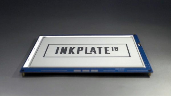
Enter the Inkplate. By pairing a recycled Kindle display with an ESP32, Croatian electronics company e-radionica says they’ve not only created an open hardware e-paper display that’s easy for hackers and makers to use, but keeps electronic waste out of the landfill. Last year the $99 USD 6 inch version of the Inkplate ended its CrowdSupply campaign at over 920% of its original goal. The new 9.7 inch model is priced at $129, and so far managed to blow past its own funding goal just hours after the campaign went live. Clearly, the demand is there.
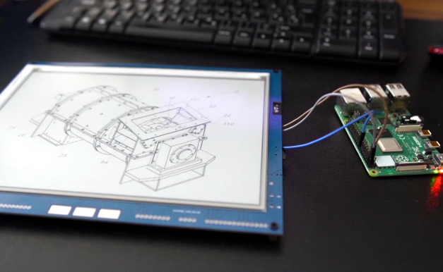 The new model’s e-paper display isn’t just larger, it also features a higher 1200 x 825 resolution and reduced refresh time. Outside of the screen improvements, you’ll also find more GPIO pins, an RTC module to keep more accurate time, and a USB Type-C port for both programming and power. You also get a choice of languages to use, with both Arduino and MicroPython libraries available for interfacing with the display. Interestingly, the Inkplate also features a so-called “Peripheral Mode” that allows you to draw graphics primitives on the screen using commands sent over UART.
While we’ve recently seen some very promising efforts to repurpose old e-paper displays, the turn-key solution offered by the Inkplate is admittedly very compelling. If you’re looking for an easy way to jump on the electronic paper bandwagon that works out of the box, this might be your chance.
[Thanks to Krunoslav for the tip.]