There’s something iconic about dish antennas. Chances are it’s the antenna that non-antenna people think about when they picture an antenna. And for many applications, the directionality and gain of a dish can really help reach out and touch someone. So if you’re looking to tap into a distant WiFi network, this umbrella-turned-dish antenna might be just the thing to build.
Stretching the limits of WiFi connections seems to be a focus of [andrew mcneil]’s builds, at least to judge by his YouTube channel. This portable, foldable dish is intended to increase the performance of one of his cantennas, a simple home-brew WiFi antenna that uses food cans as directional waveguides. The dish is built from the skeleton of an umbrella-style photographer’s flash reflector; he chose this over a discount-store rain umbrella because the reflector has an actual parabolic shape. The reflective material was stripped off and used as a template to cut new gores of metal window screen material. It’s considerably stiffer than the reflector fabric, but it stretches taut between the ribs and can still fold up, at least sort of. An arm was fashioned from dowels to position the cantenna feed-horn at the focus of the reflector; not much detail is given on the cantenna itself, but we assume it’s similar in design to cantennas we’ve featured before.
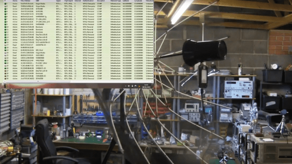
[andrew] hasn’t done rigorous testing yet, but a quick 360° scan from inside his shop showed dozens of WiFi signals, most with really good signals. We’ll be interested to see just how much this reflector increases the cantenna’s performance.
Continue reading “Umbrella And Tin Cans Turned Into WiFi Dish Antenna”