Mystery WWII Navy Gear With Magic Eye

There’s an unknown piece of military electronic gear being investigated over on [Usagi Electric]’s YouTube channel (see video below the break). The few markings and labels on the box aren’t terribly helpful, but along with the construction and parts, seem to identify it as relating to the US Navy from the WWII era. Its central feature is a seeing-eye tube and an adjustment knob. [David] does a bit of reverse engineering on the circuit, and is able to fire it up and get it working, magic eye squinting and all.

But there’s still the unanswered question, what was this thing supposed to do? Besides power, it only has one input signal. There are no outputs, except the “data” presented visually by the magic eye tube. Commenters have suggested it was used with sonar equipment, calibration tool, RTTY tuning aid, light exposure meter, etc. But if you dust off your copy of Navships 900,017 “Radar Systems Fundamentals” from 1944 and turn to page 249, there’s a section entitled Tuning Indicator that describes this circuit, almost.

Continue reading “Mystery WWII Navy Gear With Magic Eye”

Directional Antenna 3-Way

If you read old antenna books, you’ll probably see the idea of phased vertical antennas. These use certain lengths of coax to control the phase of a signal going to three verticals in a triangular configuration. Depending on the phasing, you can cause the array of antennas to be directional in one of three directions. [DX Commander] designed a very modern version of this antenna and shows the theory behind it in a recent video that you can see below.

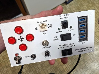
It seems another ham built the antenna and a control box for it which he’s sent to [DX Commander] although he hasn’t set it up yet to create an 80 meter directional antenna. We’ll be interested in seeing how it works in practice.

Continue reading “Directional Antenna 3-Way”

Apollo Comms Flight Hardware Deep Dive

You no doubt recall the incredible Apollo Guidance Computer (AGC) reverse engineering and restoration project featured on the CuriousMarc YouTube channel a few years ago. Well, [Marc] and the team are at it again, this time restoring the Apollo Unified S-Band tracking and communication system flight hardware. As always, the project is well documented, carefully explained, full of problems, and is proceeding slowly despite the lack of documentation.

Like the guidance computer, the Unified S-Band system was pretty innovative for its day — able to track, provide voice communications, receive television signals, and send commands to and monitor the health of the spacecraft via telemetry. The system operates on three frequencies, an uplink containing ranging code, voice and data. There are two downlinks, one providing ranging, voice, and telemetry, the other used for television and the playback of recorded data. All crammed into two hefty boxes totaling 29 kg.

So far, [Marc] has released part 9 of the series (for reference, the Apollo Guidance Computer took 27 parts plus 8 auxiliary videos). There seems to be even less documentation for this equipment than the AGC, although miraculously the guys keep uncovering more and more as things progress. Also random pieces of essential ground test hardware keep coming out of the woodwork. It’s a fascinating dive into not only the system itself, but the design and construction techniques of the era. Be sure to check out the series (part 1 is below the break) and follow along as they bring this system back to life. [Marc] is posting various documents related to the project on his website. And if you missed the AGC project, here’s the playlist of videos, and the team joined us for a Hackaday Chat back in 2020.

Continue reading “Apollo Comms Flight Hardware Deep Dive”

Affordable HF Loop Antenna Reviewed

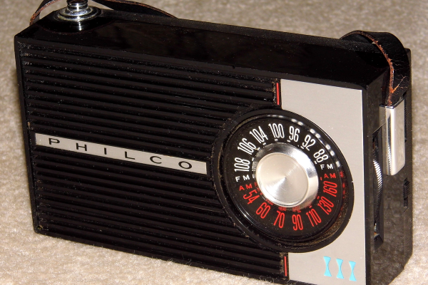
Modern ham radio operators often face restrictions on antennas. This has made small antennas more popular, despite some limitations. [Tech Minds] reviews the GA-450 indoor active HF loop antenna and finds it better than expected. You can see the video review below.

You can’t expect a little antenna to perform as well as giant skyhook. However, for such a small loop covering 3 to 30 MHz, the antenna seems to perform very well. We like that the active part of it has a rechargeable battery. Obviously, you will only want to use this antenna for receiving, but it would be a great pairing for an HF-capable software defined radio (SDR). Even just in the window sill with half gain, it was able to pick up quite a bit of signal on the 40 meter and 20 meter ham bands. According to the video, performance below 7 MHz was lackluster, but it worked nicely at higher frequencies.

The loop is directional and you can rotate the loop on the base to zero in on a particular signal. Of course, if the antenna were up in the air, it might be harder to rotate unless you work out something with a motor. If all you want to do is receive and you have a budget of under $100, this looks like it would be a nice portable option.

You can build your own loop and loop-like antennas, of course. Some of them can be quite portable.

Continue reading “Affordable HF Loop Antenna Reviewed”

A tupperware-sized 3D-printed aeroponics cell, a grid-like contraption, with about 30 cloves of garlic in it, about five of them starting to grow. The cell is printed with white plastic, and there's a semi-transparent acrylic roof with LED strips attached to its underside, lifted about 3-4 inches above the garlic.

Aeroponic Cell Grows Garlic, Forwards CellSol Packets

Certain pictures draw attention like no other, and that’s what happened when we stumbled upon a Twitter post about “resuscitating supermarket garlic” by [Robots Everywhere]. The more we looked at this photo, the more questions popped up, and we couldn’t resist contacting the author on Twitter – here’s what we’ve learned!

This is an aeroponics cell – a contraption that creates suitable conditions for a plant to grow. The difference of aeroponics, when compared to soil or hydroponics methods, is that the plant isn’t being submerged in soil or water. Instead, its roots are held in the air and sprayed with water mist, providing both plenty of water but also an excess of oxygen, as well as a low-resistance space for accelerated root growth – all of these factors that dramatically accelerate nutrient absorption and development of the plant. This cell design only takes up a tiny bit of space on the kitchen countertop, and, in a week’s time, at least half of the cloves have sprouted!

Much like a garlic bulb, this project has layers to it – in that this aeroponic cell is also a CellSol node! The CellSol project is a distributed communication system that can use LoRa and WiFi for its physical layer, enabling you to build widely spanning mesh networks that even lets you connect your smartphone to it where it’s called for – say, as an internet-connected hub for other devices to send their data through. We’ve covered CellSol and it’s hacker-friendliness previously, and one of the intentions of this design is to show how any device with a bit of brains and a SX1276 module can help you form a local CellSol network, or participate in some larger volunteer-driven CellSol-powered effort.

If, like us, you’re looking at this picture and thinking “this is something I’d love to see on my desk”, [Robots Everywhere] has published the STL files for making a hydroponic cell like this at home, as well as all the code involved, and some demo videos. Hopefully, the amount of aeroponics projects in our tips line is only going to increase! We’ve covered Project EDEN before, a Hackaday Prize 2017 entry that works to perfect an aeroponics approach to create an indoor greenhouse. There’s also a slew of hydroponics projects to have graced our pages, from hardware store-built to 3D printed ones!

Continue reading “Aeroponic Cell Grows Garlic, Forwards CellSol Packets”

Microwave Sampler Is Like Time Domain Mixer

[Gregory] is building some microwave gear and wanted to convert a 3.3 GHz signal to a 12 MHz intermediate frequency. You might think of using a mixer, but you’d need a local oscillator of nearly 3.3 GHz which is not only hard to build, but also will be very close to the signal of interest which is not a great idea. Instead, [Gregory] opted for a sampler, which uses an effect you usually try to avoid — aliasing — to allow downconversion with a much smaller local oscillator. You can see the design in the video below.

In the case of converting 3.3 GHz to 12 MHz, the local oscillator is around 100 MHz. How does that work? Watch the video and find out. The final project will triple the 3.3 GHz signal and we presume the 12 MHz downconvert is to easily phase lock the frequency using a PLL (phase-locked loop).

Continue reading “Microwave Sampler Is Like Time Domain Mixer”

Impedance Matching Revisited

If you are an old hand at RF design, you probably have a good handle on matching impedance. However, if you are just getting started with RF, [FesZ Electronic]’s latest video series on lossless impedance matching is well worth watching.

Matching is important for several reasons. Maximum power transfer occurs when the source and load impedance match. Also, at RF, mismatched impedance can cause reflections which, again, robs you of useful power. The video covers some math and then moves on to LTSpice to simulate a test circuit. But the part you are really waiting for — the practical circuits — is about 15 minutes in. Since the values you need are often oddball, [FesZ] makes his own adjustable inductors and uses a trimmer capacitor to adjust the actual capacitance value.

This is a big topic, but the first video is a great introduction blending theory, simulation, and hands-on. A great way to get started with a very fundamental RF design skill.

We’ve worked on explaining all this before if you want a second take on it. If you want to understand why mismatched impedance leads to less power delivery, we’ve done that, too.

Continue reading “Impedance Matching Revisited”