It wouldn’t be October without Halloween, and it wouldn’t be Halloween without some spooky music. There’s no instrument spookier than a Theremin, which also happens to be one of the world’s first electronic instruments.
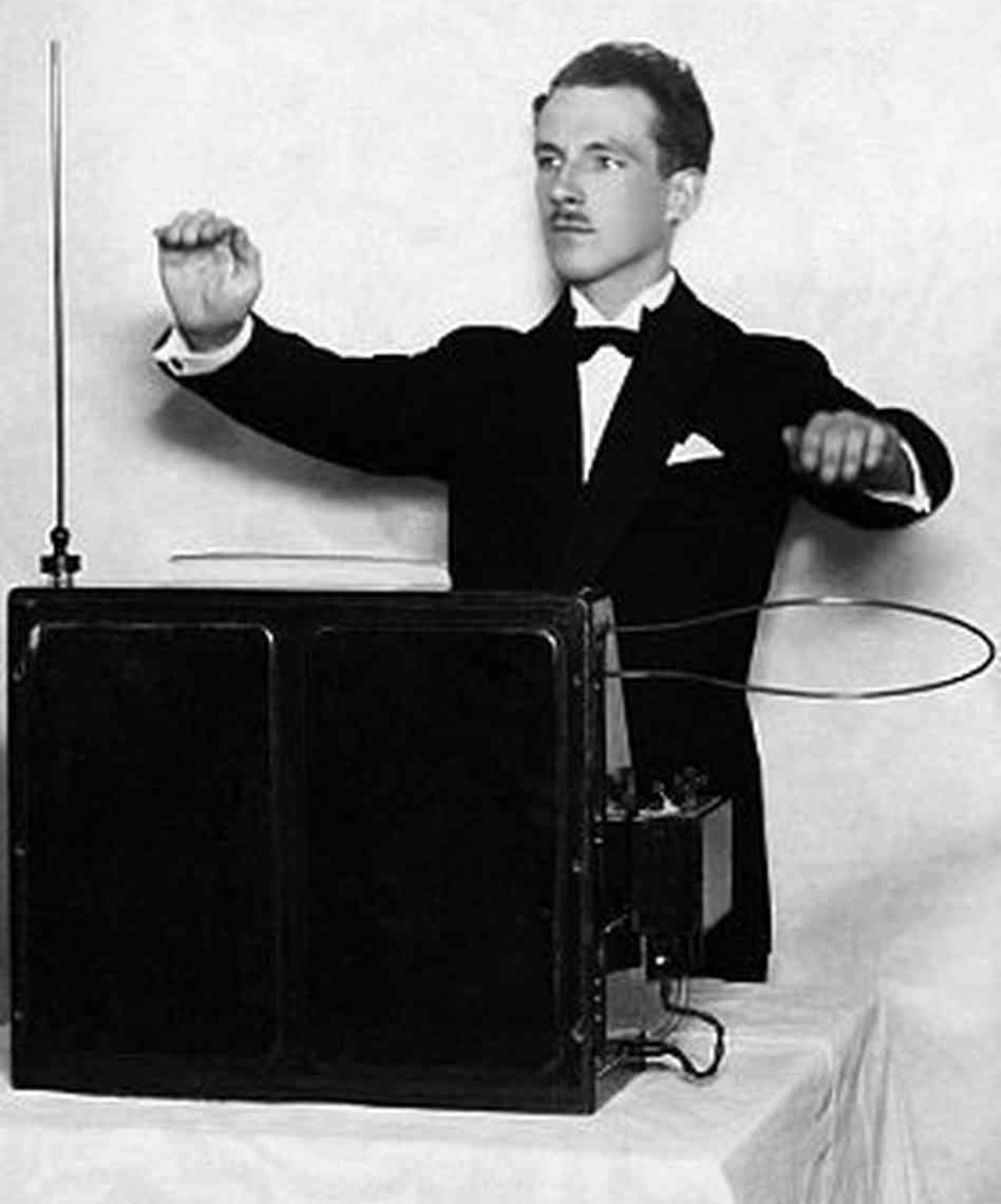
You’ve no doubt heard the eerie, otherworldly tones of the Theremin in various 1950s sci-fi films, or heard the instrument’s one-of-a-kind cousin, the Electro-Theremin in “Good Vibrations” by the Beach Boys. The Theremin turns 100 years old this month, so we thought we’d take a look at this strange instrument.
One hundred years ago, a young Russian physicist named Lev Sergeyevich Termen, better known as Leon Theremin, was trying to invent a device to measure the density of various gases. In addition to the standard analog needle readout, he wanted another way to indicate the density, so he devised an oscillator whistle that would change pitch based on the density.
He discovered by accident that having his hand in the field of the antenna changed the pitch of the whistle, too. Then he did what any of us would do — played around until he made a melody, then called everyone else in the lab over to check it out.
Theremin soon showed his device to Lenin, who loved it so much that he sent Lev on a world tour to show it off. While in New York, he played it for Rachmaninoff and Toscanini. In fact you can see a video recording of Leon playing the instrument, a performance that’s more hauntingly beautiful than spooky. In 1928, he patented the Theremin in the United States and worked with RCA to produce them.
Continue reading “The Theremin Is 100 Years Old; Celebrating The Spookiest Of Instruments”
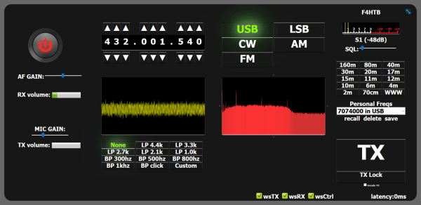
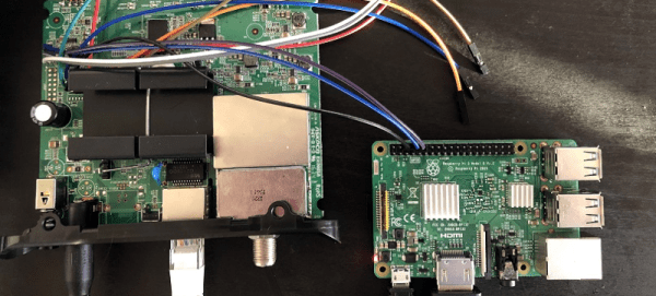
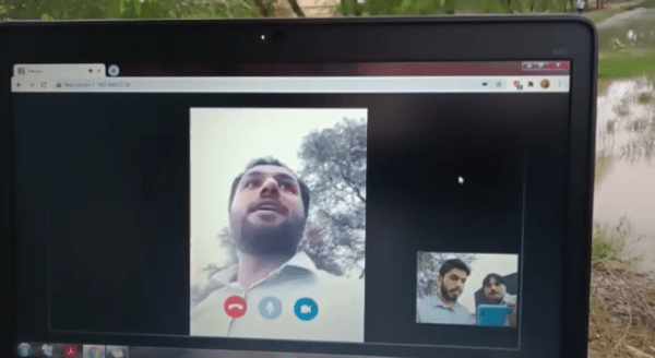
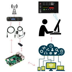 remote-controlling their rig from a laptop. As you can imagine, this essentially involves a server running on a computer hooked up to the radio, which is connected via the internet to a client running on the laptop. [Olivier/ F4HTB] saw a way to improve the process by eliminating the client software and controlling the rig from a web browser.