How Did We Get To The Speed Of Light?

Every high school physics student knows c, or the speed of light, it’s 3 x 10^8 metres per second. More advanced or more curious students will know that this is an approximation, and the figure of 299,792,458 metres per second that forms the officially accepted figure comes from a resonance of the caesium atom from which is derived a value for the second.
Galileo
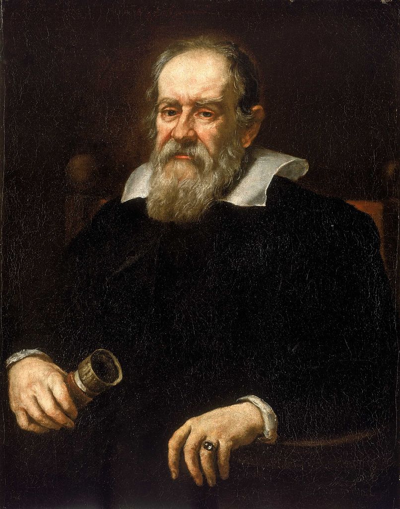
Galileo Galilei, whose presence in this story should come as no surprise. Justus Sustermans, Public domain.

But for those who are really curious about measuring the speed of light the question remains: Just how did we arrive at that figure and how long have we been measuring it? The answer contains some surprises, and some exceptionally clever scientific thought and experimentation over the centuries.

The nature of light and whether it had a speed at all had been puzzling philosophers and scientists since antiquity, but the first experiments performed in an attempt to measure it were you will not be surprised to hear, performed by Galileo sometime in the early 17th century. His experiment involved his observation of assistants uncovering lanterns at known distances away, and his observations  failed to arrive at a figure.

Later that century in 1676 the first numerical estimate of the speed of light was made by the Danish astronomer Ole Rømer, who observed an apparent variation in the period of one of Jupiter’s moons depending upon whether the Earth was approaching it or moving away from it. From this he was able to estimate the time taken for light to cross the Earth’s orbit, and from there the mathematician Christiaan Huygens was able to produce a figure of 220,000,000 metres per second.

Spinning Cogs And Mirrors: Time Of Flight
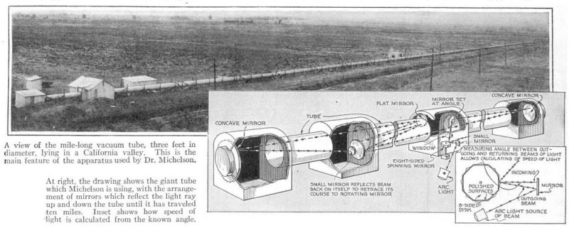
The mile-long evacuated tube used in Michelson's time-of-flight experiment. H.
The mile-long evacuated tube used in Michelson’s time-of-flight experiment. H. H. Dunn, Public domain.

The experiments with which we will perhaps be the most familiar are the so-called time of flight measurements, which take Galileo’s idea of observing the delay as light travels over a distance, and bring to it ever higher precision. This was first performed in the middle of the 19th century by the French physicist Hippolyte Fizeau, who reflected a beam of light from a mirror over several kilometres, and used a toothed wheel to chop it into pulses. The pulses could be increased in frequency by moving the wheel faster until the time taken for the light to travel the distance from wheel to mirror and back again matched the separation between teeth and the returning pulse could be observed. His calculation of 313,300,000 metres per second was successively improved upon through the work of succession of others including Léon Foucault, culminating in the series of experiments by the American physicist Albert A. Michelson in the 1920s. Michelson’s final figure stood at 299,774,000 metres per second, measured through a multi-path traversal of a mile-long evacuated tube in the California desert. In the second half of the century the techniques shifted to laser interferometry, and in the quest to define the SI units in terms of constants, eventually to the definition mentioned in the first paragraph.

The most fascinating part of the story probably encapsulates the essence of scientific discovery, namely that while to arrive at something takes the work of many scientists building on the work of each other, it can then often be rendered into a form that can be understood by a student who hasn’t had to pass through all that effort. We could replicate Fizeau and Michelson’s experiments with a pulse generator, laser diode, and oscilloscope, which while of little scientific value nearly a century after Michelson’s evacuated tube, is still immensely cool. Has anyone out there given it a try?

Header image: Tommology, CC BY-SA 4.0.

Cranes made by Origami (Orizuru). The height is 35mm.

Bringing The Art Of Origami And Kirigami To Robotics And Medical Technology

Traditionally, when it comes to high-tech self-assembling microscopic structures for use in medicine delivery, and refined, delicate grippers for robotics, there’s been a dearth of effective, economical options. While some options exist, they are rarely as effective as desired, with microscopic medicine delivery mechanisms, for example, not having the optimal porosity. Similarly, in so-called soft robotics, many compromises had to be made.

A promising technology here involves the manipulation of flat structures in a way that enables them to either auto-assemble into 3D structures, or to non-destructively transform into 3D structures with specific features such as grippers that might be useful in both micro- and macroscopic applications, including robotics.

Perhaps the most interesting part is how much of these technologies borrow from the Japanese art of origami, and the related kirigami.

Continue reading “Bringing The Art Of Origami And Kirigami To Robotics And Medical Technology”

Raspberry Pi And The Story Of SD Card Corruption

Tales of Raspberry Pi SD card corruption are available online by the fistful, and are definitely a constant in Pi-adjacent communities. It’s apparent that some kind of problems tend to arise when a Raspberry Pi meets an SD card – which sounds quite ironic, since an SD card is the official and recommended way of booting a Pi. What is up with all of that?

I can start with a history lesson. Back when Raspberry Pi launched in 2012 – which is now 10 years ago – there were SD card controller driver problems, which makes sense given the wide variety of SD cards available out there. They were verifiably fixed one by one at some point in time, as debugging goes, their impact decreased and bugs with individual cards got smoothed over. This is how the “Pi SD card corruption” meme was originally born; however, if the problems were to end there, so would the meme. Yet, tales of broken SD cards plague us to this day – way less severe than they were in the beginning, but pronounced enough that you’ll see people encounter them every now and then.

Over the years, a devoted base of Pi SD card haters has grown. Their demand has been simple – Raspberry Pi has to get an ability to boot from something else, in large part because of corruption reasons, but also undeniably because of speed and capacity/cost limitations of SD cards. Thanks to their demands and work, we’ve seen a series of projects grow from unofficial efforts and hacks into officially supported Raspberry Pi abilities – USB boot being initially more of a workaround but now something you can enable out of the box, SSD-equipped Pi enclosures becoming more of a norm, and now, NVMe boot appearing on the horizon. Every few years, we get a new way to boot a Pi. Continue reading “Raspberry Pi And The Story Of SD Card Corruption”

The Light Guide Hiding In Your Extrusion

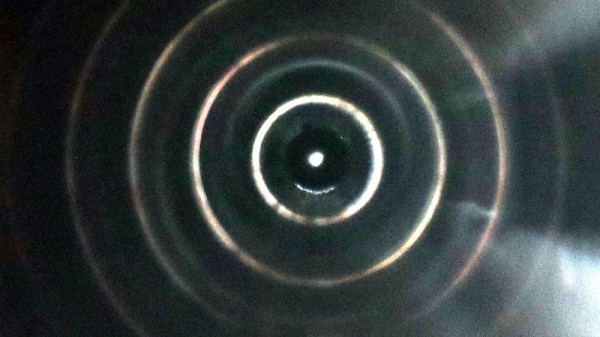
There should be a line of jokes that start “A physicist and an engineer walk into a bar…”. In my case I’m an engineer and my housemate is a physicist, so random conversations sometimes take interesting turns. Take the other day for example, as one does when talking she picked up a piece of aluminium extrusion that was sitting on our coffee table and turned it over in her hands. It has a hole down its centre and it’s natural to peer down it, at which point her attention was caught by the appearance of a series of concentric rings of light. Our conversation turned to the mechanism which might be causing this, and along the way took us into cameras, waveguides, and optical fibres.

The light reaching us after traveling along a straight narrow tube should at a cursory glance be traveling in a straight line, and indeed when I point the extrusion out of my window and look down it I can see a small segment of the tree in the distance I’ve pointed it at. It didn’t take us long to conclude that the concentric rings were successive reflections of the light coming into the end hole from off-centre angles.

In effect, the extrusion is a pinhole camera in which the image is projected onto the inside of a cylinder stretching away from the pinhole rather than onto a flat piece of film, and we were seeing the successive reflections of the resulting distorted image as they bounced to and fro down the tube towards us. It’s likely the imperfect mirror formed by the aluminium wall allowed us to see each image, as light was being diffused in our direction. Adding a piece of tape with a small pinhole at the end accentuated this effect, with the circles becoming much more sharply defined as the projected image became less blurry. Continue reading “The Light Guide Hiding In Your Extrusion”

Grid Batteries On Wheels: The Complicated Logistics Of Vehicle-Grid Integration

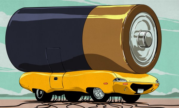
At its core, the concept of vehicle-grid integration (VGI) – also called Vehicle To Grid (V2G) – seems a simple one. Instead of a unidirectional charger for battery-electric vehicles (BEVs), a bidirectional charger would be used. This way, whenever the BEV is connected to such a charger, power could be withdrawn from the car’s battery for use on the local electrical grid whenever there’s demand.

Many of the complications with VGI have already been discussed, including the increased wear that this puts on a BEV’s battery, the need for an inherently mobile machine to be plugged into a charger, and the risk of needing one’s BEV and finding its battery to be nearly depleted. Here the cheerful marketing from Nissan and that from commercial initiatives such as Vehicle to Grid Britain makes it sound like it’s a no-brainer once those pesky details can be worked out.

In parallel with the world of glossy marketing leaflets, researchers have been investigating VGI as a potential option for grid-level energy storage. These studies produce a far less optimistic picture that puts the entire concept of VGI into question.

Continue reading “Grid Batteries On Wheels: The Complicated Logistics Of Vehicle-Grid Integration”

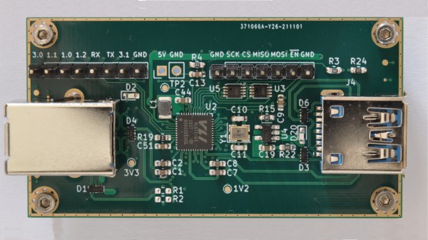
Top side of the VL670 breakout board, with two USB connectors and the VL670 chip in the center.

A Chip To Bridge The USB 2 – USB 3 Divide

On Twitter, [whitequark] has  found and highlighted an intriguing design – a breakout board for the VL670, accompanied by an extensive yet very easy to digest write-up about its usefulness and inner workings. The VL670 is a chip that addresses a surprising problem – converting USB 2.0 signals into USB 3.0.

If you have a USB 2.0 device and a host with only USB 3.0 signals available, this chip is for you. It might be puzzling – why is this even needed? It’s about the little-known dark secret of USB3, that anyone can deduce if they ever have to deal with a 9-pin USB 3.0 connector where one of the three differential pairs doesn’t quite make contact.

When you see a blue “3.0” port, it’s actually USB 2 and USB 3 — two separate interfaces joined into a single connector. USB 3 uses two single-directional differential pairs, akin to PCI-E, whereas USB 2 uses a single bidirectional one, and the two interfaces on a blue connector operate basically independently of each other. There’s many implications to this that are counterintuitive if you simply take “USB 3.0” for “faster backwards-compatible USB”, and they have painful consequences.

For instance, USB 3 hub ICs have two separate hub entities inside – one for USB 3 and one for USB 2. Even if you have a USB 3 hub plugged into a USB 3 port, multiple USB 2 devices plugged into it still cannot break through the USB 2 uplink limit of 480 MBps. If you ever thought that a faster hub with a faster uplink would fix your USB 2 device speed problems – USB-IF engineers, apparently, thought differently; and you might have to find a workaround for your “many cheap SDRs and Pi 4 in a box” setup. Continue reading “A Chip To Bridge The USB 2 – USB 3 Divide”

Metal 3D Printing Hack Chat

Join us on Wednesday, March 9 at noon Pacific for the Metal 3D Printing Hack Chat with Agustin Cruz!

3D printing has been an enabling technology, and the ability to create parts that never existed anywhere before has been a real game-changer. But the cheap and readily accessible FDM and SLA printers we’ve come to depend on are not without their drawbacks, chief among which is that they only make plastic parts. Wouldn’t it be great if we home-gamers had the ability to print metal parts just like they do in industry? Agustin Cruz thinks so, and he’s been hard at work on an electron-beam sintering printer to make that dream come true. Dealing with the technical challenges of such a printer hasn’t been easy, but then again, squeezing out melted plastic wasn’t easy at first either.

join-hack-chatAgustin has agreed to take a little time out of his project to talk to us about his progress, and to share what he has learned about electron-beam printing. Along the way, we’ll talk about metal printing in general, and perhaps even take a look at where the whole field is going and how — and when — it’ll penetrate the hobby printing market.

Our Hack Chats are live community events in the Hackaday.io Hack Chat group messaging. This week we’ll be sitting down on Wednesday, March 9 at 12:00 PM Pacific time. If time zones have you tied up, we have a handy time zone converter.
Continue reading “Metal 3D Printing Hack Chat”