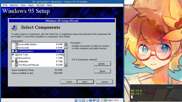
Mastering OpenSCAD Workflow

As you may have noticed in our coverage, we’re big fans of OpenSCAD around these parts. The fact that several of the Hackaday writers organically found and started using the parametric CAD package on their own is not only a testament to our carefully cultivated hive mind but also to the type of people it appeals to. Hackers love it because it allows you to model physical objects as if you were writing software: models are expressed in code, and its plain text source files can be managed with tools like git and make. If you’re a real Pinball Wizard you could design objects and export them to STL without ever using a graphical interface.

But as you might expect, with such power comes a considerable learning curve. OpenSCAD devotee [Uri Shaked] recently wrote in to share with us his workflow for designing complex interacting mechanisms, which serves as an excellent primer to the world of parametric design. From animating your models to recreating the “vitamins” of your build, his post contains plenty of tips that can help both new and veteran OpenSCAD users alike.

Perhaps the biggest takeaway from his post is that you should be thinking of your projects as a whole, rather than as individual models. [Uri] recalls his early attempts at designing mechanisms: designing each component individually, printing it out, and only then finding out if it fits together with the other pieces. This method of trial and error is probably familiar to anyone who’s designed their own 3D printed parts — but it’s slow and wastes materials. The alternative, as he explains it, is to design all of the pieces at the same time and “assemble” them virtually. This will allow you to check clearances and fitment without dedicating the time and materials to test it in the real world.

In fact, as [Uri] explains, you’re better off spending your time bringing real-world parts into OpenSCAD. By carefully measuring the hardware components you want to interact with (servos, gears, switches, etc), you can create facsimiles of them to use as a reference in your OpenSCAD project. As time goes on, you can build up your own library of drop-in reference models which will accelerate future designs.

He also spends a little time talking about something that doesn’t seem to be terribly well known even among the OpenSCAD converts: you don’t have to use the built-in editor if you don’t want to. Since OpenSCAD source code files are plain text, you can write them in whatever editor you like. The OpenSCAD model viewer even has an option specifically for this scenario, which will cause it to update the rendered preview as soon as it detects the source has been updated. For [Uri] this means he can create his designs in Visual Studio Code with a constantly updating preview in another window.

If you’re looking for examples of what the parametric capabilities of OpenSCAD can do for you, we’ve got no shortage of excellent examples. From creating customized computer cases to saving time by using mathematically derived components. Our very own [Elliot Williams] even has a write up about that most glorious of OpenSCAD commands: hull().

BitBench Helps Parse Binary Data

Maybe its a capture file from a network dump. Maybe it’s from an Arduino. Maybe it is a random file off the Internet. But there will be a time when you have a file full of seemingly meaningless numbers and you need to impose order. We usually resort to a printout and highlighter, but BitBench seems like a better option. That link will take you to the code, but if you want to play with a live instance, the author has one loaded with example data.

If you look at the live example, there’s an area up top with a lot of raw hex data. The area below that shows a format string. By default that’s:

hh ID:hh b CH3d TEMP_C:12d HUM:d CRC:8h | 8h 16h 16h

From the page, here’s the description of the format:

Use “h” for hex (default 4 bits), “b” for binary (default 1 bit), “d” for decimal (default 8 bits).
Use optional bit length prefix numbers. Use “~” to invert bits, use “^” to reverse LSB/MSB. Other characters are output as-is.

So in the example string, hh is an 8-bit hex number. ID: is just a label, followed by another 8-bit number.  Then the bottom displays the data formatted as you wish and gives you a way to pad the fields with extra bits and see the results. You can also invert or shift all the bits.

Continue reading “BitBench Helps Parse Binary Data”

An OpenSCAD Mini-ITX Computer Case

We’re no strangers to 3D printed enclosures here at Hackaday. From the plethora of printed Raspberry Pi cases out there to custom enclosures for electronic projects, small plastic boxes turn out to be an excellent application for desktop 3D printing. But as printers get bigger and filament gets cheaper, those little boxes don’t always need to be so little. We aren’t talking about running off boxes for your sneaker collection either, if you’ve got the time and the print volume, you could whip up an enclosure for your PC.

[Nirav Patel] writes in to share his impressive 3D printed Mini-ITX computer case project, which would be a neat enough trick in its own right, but he took the concept one step farther and made it a parametric design in OpenSCAD. This allows the user to input their particular hardware configuration and receive STL files for a bespoke case. The list of supported hardware isn’t that long yet, but with the OpenSCAD code up on GitHub and released under the BSD license, hopefully the community can improve on that as time goes on.

To keep things simple (and strong), [Nirav] implemented what he refers to as a “bucket” design. The majority of the case is a single print, which does take a long time (just shy of 40 hours on his Prusa i3 MK3), but nearly eliminates any post-printing assembly. Only the optional feet and the lid need to be printed separately. Threaded inserts are used throughout the design for mounting hardware, so you don’t run the risk of blowing out the printed holes during hardware changes or upgrades.

A particularly neat feature, and a testament to the power of OpenSCAD, is the fact that the case’s internal volume is calculated and embossed into the side of the design. Does this have any practical purpose? Not exactly, but [Nirav] thought it would be appealing to the Mini-ITX case modding community which apparently measures their accomplishments in liters of volume.

We’ve seen a 3D printed computer case before, but it used acrylic sheets and couldn’t be made without a large format printer. There’s something to be said for a project that can be completed on the hacker community’s favorite printer.

A QR Code, Step By Step

We should all be familiar with QR codes, those blocky printed patterns containing encoded text, URLs, or other data. A few years ago they were subject to their own cloud of hype, but now they have settled down in their niche of providing a handy route for a smartphone owner to reach a website without having to type an address.

Have you ever wondered how they work? There are plenty of dry technical guides out there, but if they’re not your thing you might find [Nayuki]’s step-by-step guide to be of interest. It explains the encoding and error checking bit generation process before starting on the familiar three-squares pattern and timing bars of the QR code itself. The really interesting part comes with its explanation of overlays, a set of repeating patterns that are added to the final data segment, and how the pattern used is chosen to minimise penalties due to large blocks of the same colour in the final piece. The chances are most of us will never have to create a QR code from scratch, but it is this type of fascinating technical general knowledge that makes guides like this such an interesting read.

QR codes have appeared in quite a few projects here over the years, but the one we find particularly amusing is this project to hack them by changing one QR into another.

Via Hacker News.

Adaptive Layer Height On The Monoprice Select Mini

If you’ve used a desktop 3D printer, you’re likely familiar with the concept of layer heights. Put simply: thicker layers will print faster, and thinner layers will produce better detail. Selecting your layer height is making a choice between detail and speed, which usually works well enough. For example, prints which are structural and don’t have much surface detail can be done in higher layer heights to maximize speed with no real downside. Conversely, if you’ve got a model with a lot of detail you’ll have to just deal with the increased print time of thinner layers.

At least, that’s how it’s been up till now. Modern slicer software is starting to test the waters of adaptive layer heights, which change the layer height during the print. So the software will raise or lower the layer height depending on the level of detail required for the current area being printed. [Dylan Radcliffe] wanted to experiment with this feature on his Monoprice Select Mini, but it took some tweaking and the dreaded mathematics to get Cura’s adaptive layer height working on the entry-level printer. He’s documented his settings for anyone who wants to check out this next-generation 3D printing technology without forking out the cash for a top of the line machine.

While Cura is a popular slicer, the fact of the matter is that it’s developed by Ultimaker primarily for their own line of high-end printers. It will control machines from other manufacturers, but it makes no promises that all the features in the software will actually work as expected on lesser printers. In the case of the Monoprice Mini, the issue is the rather unusual Z hardware. The printer uses a 7.5° 48-step motor coupled to 0.7 mm thread pitch M4 rod. This is a pretty suspect arrangement that was no doubt selected to keep costs down, and results in an unusual 0.04375 mm step increment. For the best possible print quality, layer heights should be a multiple of this number. That’s where the math comes in.

After enabling adaptive layers in Cura’s experimental settings, you need to define the value which Cura will add or subtract to the base layer height. In theory you could enter 0.04375 mm here, but while that’s the minimum on paper, the machine itself is unlikely to be able to pull off such a small variation. [Dylan] recommends doubling that to 0.0875 for the “variation step size” parameter, and setting the base layer height to 0.175 mm (4 x 0.04375 mm).

[Dylan] reports these settings reduced the print time on his topographical map pieces from 12 hours to 7 hours, while still maintaining high detail on the top surface. Of course print time reduction is going to be highly dependent on the model being printed, so your mileage may vary.

If Cura isn’t your style, our very own [Brian Benchoff] gave us a tour of “variable layer height”, the Slic3r version of this technique. Perfect for that Prusa i3 MK3 you finally spent the cash on.

Jump Into AI With A Neural Network Of Your Own

One of the difficulties in learning about neural networks is finding a problem that is complex enough to be instructive but not so complex as to impede learning. [ThomasNield] had an idea: Create a neural network to learn if you should put a light or dark font on a particular colored background. He has a great video explaining it all (see below) and code in Kotlin.

[Thomas] is very interested in optimization, so his approach is very much based on mathematics and algorithms of optimization. One thing that’s handy is that there is already an algorithm for making this determination. He found it on Stack Exchange, but we’re sure it’s in a textbook or paper somewhere. The existing algorithm makes the neural network really impractical, but it makes training easy since you can algorithmically develop a training set of data.

Once trained, the neural network works well. He wrote a small GUI and you can even select among various models.

Don’t let the Kotlin put you off. It is a derivative of Java and uses the same JVM. The code is very similar, other than it infers types and also adds functional program tools. However, the libraries and the principles employed will work with Java and, in many cases, the concepts will apply no matter what you are doing.

If you want to hardware accelerate your neural networks, there’s a stick for that. If you prefer C and you want something lean and mean, try TINN.

Continue reading “Jump Into AI With A Neural Network Of Your Own”

Use Nodes To Code Loads Of G-code For 3D CNC Carving

Most CNC workflows start with a 3D model, which is then passed to CAM software to be converted into the G-code language that CNC machines love and understand. G-code, however, is simple enough that rudimentary coding skills are all you need to start writing your very own programmatic CNC tool paths. Any language that can output plain text is fully capable of enabling you to directly control powerful motors and rapidly spinning blades.

[siemenc] shows us how to use Grasshopper – a visual node-based programming system for Rhino 3D – to output G-code that makes some interesting patterns and shapes in wood when fed to a ShopBot. Though the Rhino software is a bit expensive and thus is not too widely available, [siemenc] walks through some background, theory, and procedures that could be useful and inspirational no matter what software or programming language you’re using to create your bespoke G-code.

For links to code and related blog posts, plus more lovely pictures of intricately carved plywood, check out [siemenc]’s personal site as well.

[via Bantam Tools]