If you’ve ever been to the dental surgery and found yourself requiring some gum surgery, the chances are you’ll have found your dentist wielding an electronic probe to cauterise the flesh. It’s evidently some form of RF device because you are usually required to hold one of the electrodes while it’s being used, but annoyingly, for an engineer, it’s hardly the time or place to ask how it works. For the curious, then, [Keri Szafir] has the box of tricks behind the probe and is subjecting it to a teardown.
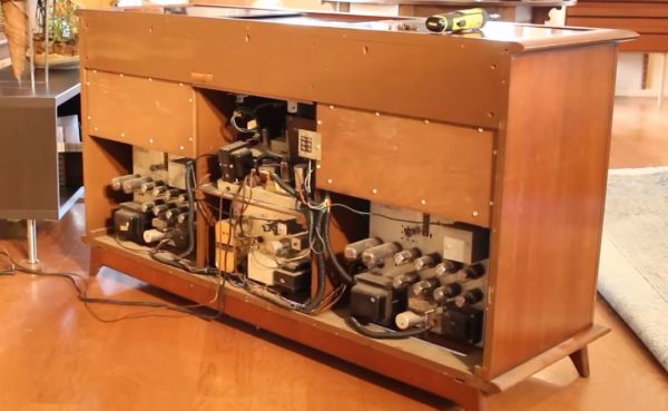
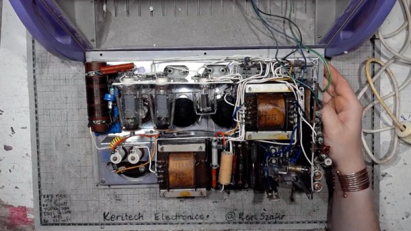
The box on her bench isn’t the one you’ll find in your dentist’s toolkit today, but its distant ancestor from the 1960s that integrates multiple functions into a single box. It’s a very period enclosure with typically 1960s-style vacuum tubes and point-to-point wiring. There’s an HF oscillator using a pair of EL81 power pentodes for that electrode you always wished you could ask your dentist about, and unexpectedly, a thyratron, a type of gas-filled switching tube not dissimilar to a thyristor, in a separate circuit for dental pulp testing. We’re not dental experts here at Hackaday, but [Keri] has done the research and explains the device in the video below the break. At one point, she observes that it’s quite a scary machine to be connected to a living person, and we can concur with that.
Her bench has provided a few projects here in the past, including one of her amplifiers. While it might be fun to tear down a more modern version, you are better off asking for old dental burrs.
Continue reading “The Height Of 1960s Dental Electronic Technology”